|
|
4051 Mux/demux
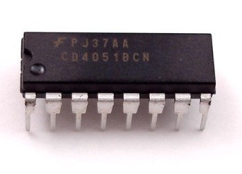
A multiplexer or demultiplexer enables you to expand the in-and outputs on your Arduino board. The 4051 is an 8 channel analog multiplexer / demultiplexer, thus:
If you use the 4051 as a Multiplexer: You can choose between 8 different inputs and select just one you want to read at the time.
If you use the 4051 as a Demultiplexer you can choose between 8 different outputs and select just one you want to write at the time.
Futhermore, the 4051 is able to work with analog values; in the case of the Arduino, you are able to use the analog inputs with a voltage between 0-5V and route them to an Analog-In Pin on your Arduino.
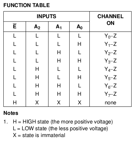
To select the Pin we would like to read or write, we have to use the three Select Pins (S0, S1 and S2). Each of these pins have to be connected to one digital out pin on the Arduino. Every pin is representing a number (S0 = 1; S1 = 2; S2 = 4) and if we set one of these Select pins to HIGH, the number the pin is representing will be transmitted to the 4051. For example:
-
If S0 and S1 are HIGH and S2 is LOW pin y3 is selected (1+2+0 = 3).
-
If S0 and S2 is HIGH and S1 LOW pin y5 is selected (1+0+4 = 5).
It is not possible to read or write more than one pin on the 4051 at the same time, because you can only select one pin at a time. But you can read and write to the pins quite fast. There is no delay needed between selecting and read or writing the pin.
Datasheet
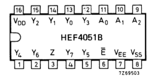
VDD - Suplpy from 3V to 15V;
VSS - GND;
VEE - GND;
A0,A1,A2 - address ports;
Y0,Y1...Y6,Y7 - I/O ports;
Z - common input or output;
E - Enable.
Remember that you have to connect the E pin to ground, to enable the circuit.
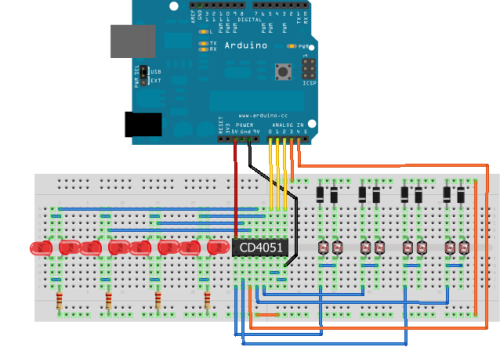
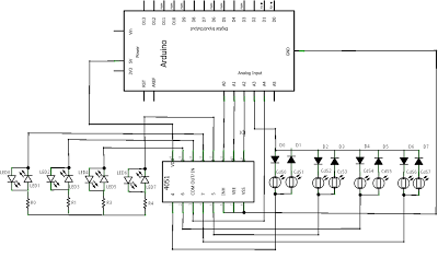
Here we are using LDRs, but you can use potentiometers or resistors. Cover the LDR and the corresponding LED will turn on.
Code
/*
 * Example of getting 16 i/o from 5 pins using a CD4051
 *
 * Based on tutorial and code by david c. and tomek n.* for k3 / malmö högskola
 * http://www.arduino.cc/playground/Learning/4051?action=sourceblock&a...
 */


int selPin[] = { 14, 15, 16 }; // select pins on 4051 (analog A0, A1, A2)
int commonPin[] = { 17, 18};   // common in/out pins (analog A3, A4)
int led[] = {LOW, LOW, LOW, LOW, LOW, LOW, LOW, LOW };  // stores eight LED states
int CdSVal[] = { 0, 0, 0, 0 }; // store last CdS readings
int cnt = 0;  // main loop counter
int persistDelay = 100; // LED ontime in microseconds


void setup(){
  Serial.begin(9600);  // serial comms for troubleshooting (always)
  for(int pin = 0; pin < 3; pin++){ // setup select pins
    pinMode(selPin[pin], OUTPUT);
  }
}


void loop(){
  flashLEDs();
  if (cnt == 0){
    for(int x; x < 8; x++){
      led[x] = random(2);
    }
  }
  cnt++;
  if (cnt > 100) { cnt = 0; }
}


void flashLEDs() {
  for(int pin = 0; pin < 2; pin++) {  // set common pins low
    pinMode(commonPin[pin], OUTPUT);
    digitalWrite(commonPin[pin], LOW);
  }
  for (int bank = 0; bank < 4; bank++) {
    for(int pin = 0; pin < 3; pin++) { // parse out select pin bits
      int signal = (bank >> pin) & 1;  // shift  & bitwise compare
      digitalWrite(selPin[pin], signal);
    }
    if (led[bank * 2]){        // first LED
      digitalWrite(commonPin[0], HIGH);  // turn common on
      delayMicroseconds(persistDelay);   // leave led lit
      digitalWrite(commonPin[0], LOW);   // turn common off
    }
    if (led[bank * 2 + 1]){     // repeat for second LED
      digitalWrite(commonPin[1], HIGH);
      delayMicroseconds(persistDelay);
      digitalWrite(commonPin[1], LOW);
    }
  }
}
int r0 = 0;      //value of select pin at the 4051 (s0)
int r1 = 0;      //value of select pin at the 4051 (s1)
int r2 = 0;      //value of select pin at the 4051 (s2)
int count = 0;   //which y pin we are selecting

void setup(){
  pinMode(2, OUTPUT);    // s0
  pinMode(3, OUTPUT);    // s1
  pinMode(4, OUTPUT);    // s2
}

void loop () {
  for (count=0; count<=7; count++) {
    // select the bit
    r0 = bitRead(count,0);    // use this with arduino 0013 (and newer versions)
    r1 = bitRead(count,1);    // use this with arduino 0013 (and newer versions)
    r2 = bitRead(count,2);    // use this with arduino 0013 (and newer versions)

    //r0 = count & 0x01;      // old version of setting the bits
    //r1 = (count>>1) & 0x01;      // old version of setting the bits
    //r2 = (count>>2) & 0x01;      // old version of setting the bits

    digitalWrite(2, r0);
    digitalWrite(3, r1);
    digitalWrite(4, r2);

    //Either read or write the multiplexed pin here
  }
}
ref:
arduino.cc
garagelab.com
hackerstore.nl
dawson-station.blogspot.nl
|