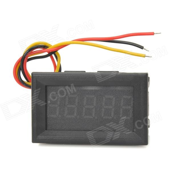
Digital voltmeter
- Model: 7042
- Quantity: 1
- Color: Black
- Material: Plastic + iron + PCB
- Measurement range: DC 0~33V
- Display: 5-digit 0.36 LED digital tube
- Display color: Red
- Refresh speed: > 5times per second
- Power supply voltage: DC 3.5~30V (Independent power supply)
- Working temperature: -10'C~65'C
- Temperature Coefficient: < 25 PPM/'C
- Ideal for DIY project.
- Cable length: 14cm
Connector P1 is a three wire connector for the red, black and white wires. Nobody is able to categorically tell you which colours relate to the three pins but the three pins are: -
Pin 1 on P1 is ground
Pin 2 on P1 is battery or dc supply to power the LED display and chips - it needs to be 4.5V to 30V.
Pin 3 on P1 is the pin that you use to measure a voltage so that its value can be displayed on the LED display.
The answer is: black is - (negative) and red is display + (positive), and white is the wire that the voltage is measured off of. How I came to this conclusion, was I asked my wife, who has absolutely no electrical background and is deathly afraid of electricity. lol. So I decided to test this for myself. I put the black on ground and the hot on red - the meter lights came on and displayed 0.0 volts. So then I added the white wire to the red one that was on hot - it displayed the voltage. so the last test just to be sure? Add a ground from another DC source and a hot from that other source to just the white wire and leave the red on the hot from the other battery? Can you guess what happened? Yes! Exactly, it showed the voltage of the new source on the white wire and not use the power from white to light the device. Instead lighting its self from the red and measuring from the white. :)