The DCC Monitor
MynaBay is developing an Arduino library for model railroad DCC projects. DCC monitors, accessory decoders and even mobile decoders can be built using the Arduino. This source code is being given to the model railroad world as public domain. You're free to do whatever to want, using this as a starting point. Our plan is continue to expand the library and add more examples.
To begin, you'll need to install the Arduino IDE from
www.arduino.cc. You'll find the download and complete instructions for your environment there. It's recommended that you install the IDE and run some of the default examples on an Arduino before tackling the DCC Monitor.
DCC specifications contain DCC packet format details. Visit
NMRA.org for more details.
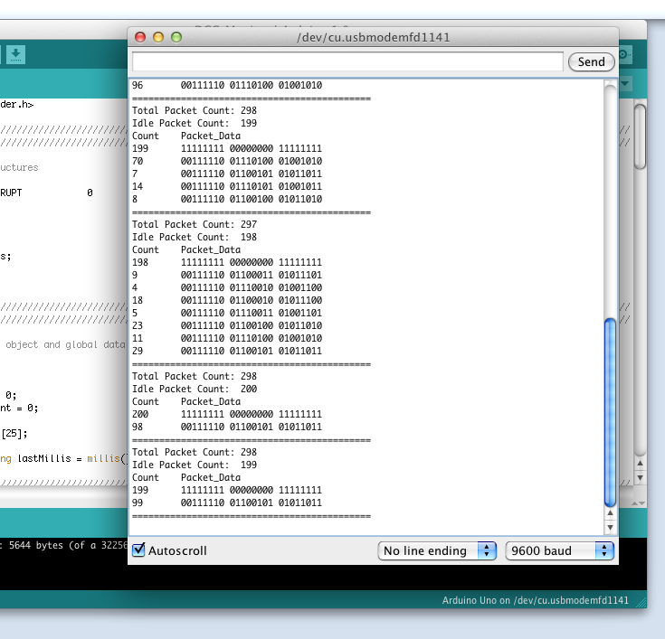
The DCC Monitor will parse the DCC signal and count packets. Every two seconds the data is dumped out the serial monitor on your computer.
We built a DCC monitor using an Arduino Uno and a few components.
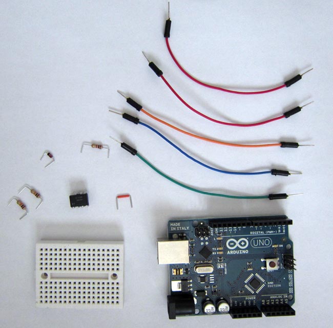
Parts Needed:
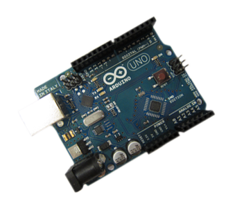
- Arduino Uno
- Small breadboard
- 2 - 10K resistors
- 1 - 1K resistor
- 1 - Diode 1N4148
- 1 - Optoisolator 6N137
- 6 - Jumper wires
Digi-Key is a great place to purchase the optoisolator, diode and resistors.
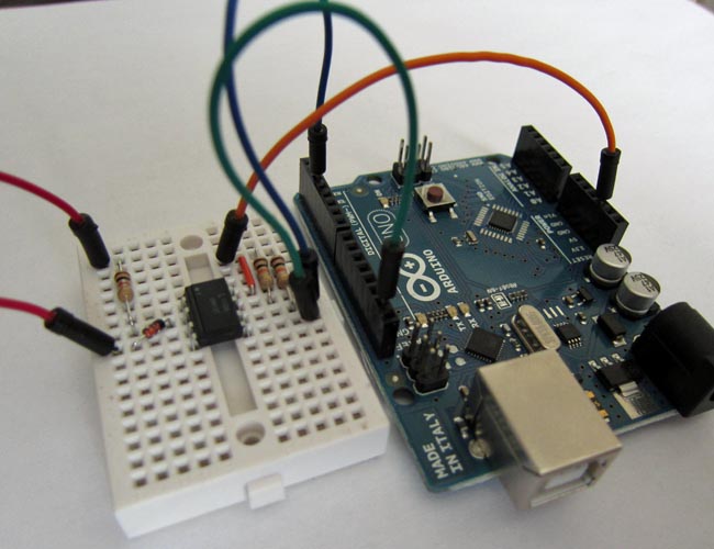
We'll start by building this circuit. A big thanks to Dave Falkenburg for providing this circuit to us. It made this project possible.
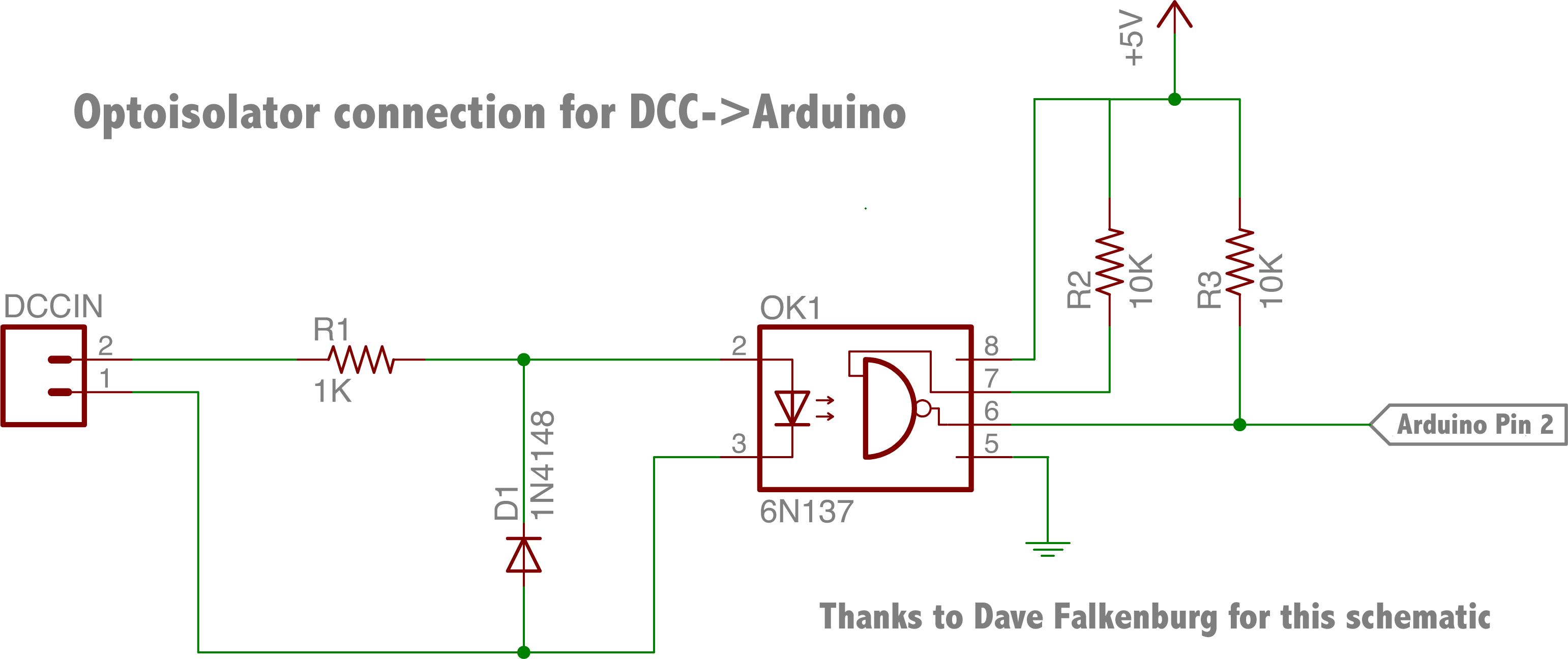
The DCCIN connections are the two rails where you want to monitor the DCC signal. This signal is run through an optoisolator (6N137). This protects the Arduino from the higher voltages on the rails. The output of the optoisolator is connected to pin 2 on the Arduino. This pin drives interrupt 0 on the Arduino, software takes it from there.
We'll be building this circuit on the breadboard and connecting to the Arduino Uno.
Hardware
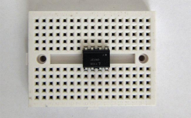
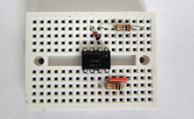
Step 1 Place the optoisolator on the breadboard. Pin 1 has a little dot above it.
 Step 2
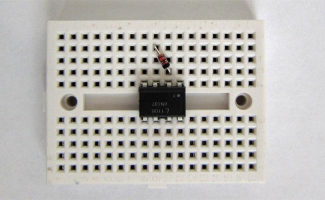
 Place the diode between pins 2+3 on the optoisolator. The orientation of a diode matters. Make sure you have it facing the right direction.
 Step 3
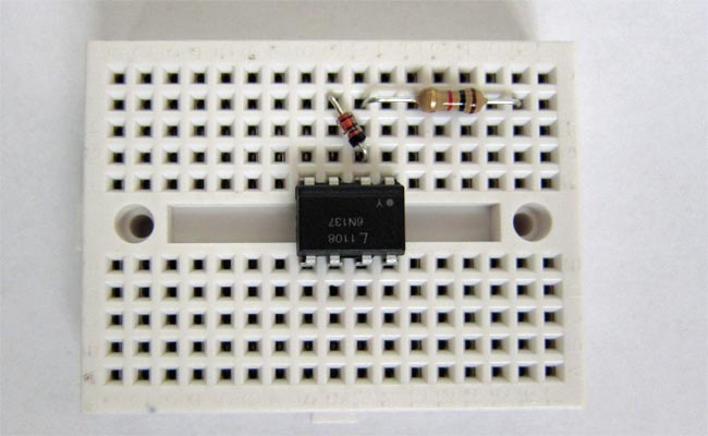
 Place the 1K resistor from pin 2 to an unused slot.
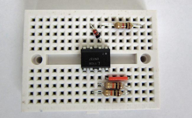
 Step 4
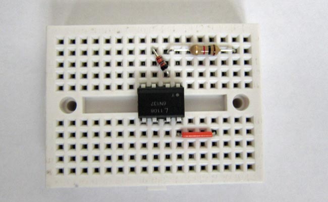
 Insert a small jumper from pin 8 to an unused slot. This slot we'll refer to a +5v.
 Step 5
 Place a 10K resistor between pin 7 and +5v slot from step 4.
 Step 6
 Place the other 10K resistor between pin 6 and +5v slot.
 Step 7
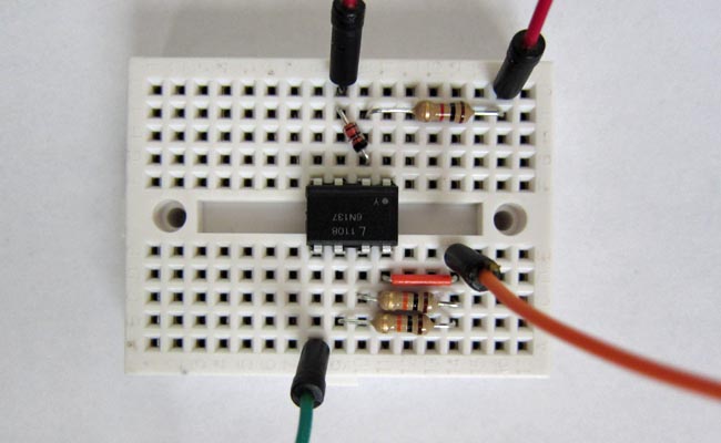
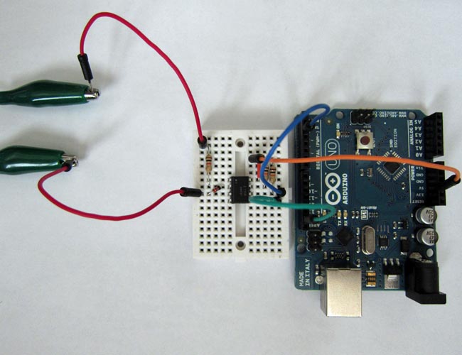
 Place jumpers (we used red) to attach to the input signal. One on pin 3 and the other to the unused slot from step 3. These are the connection to DCC signal, or simply the rails.
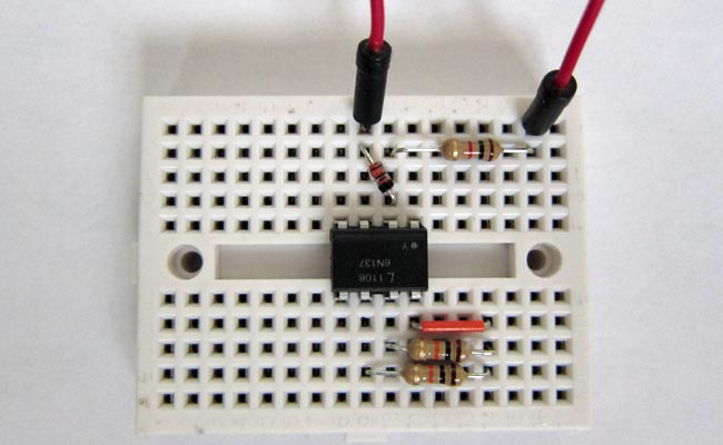 Step 8
 Attach a jumper (we used orange) to attach to +5v on the Arduino.
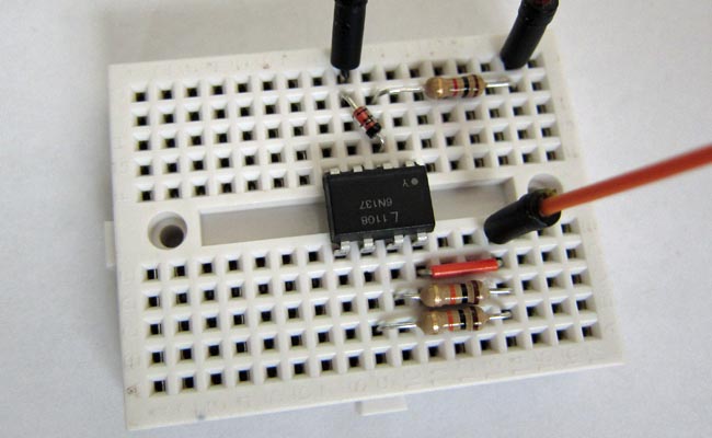 Step 9
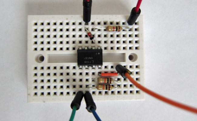
 Attach a jumper (we used green) to pin 5. This will attach to gnd on the Arduino.
 Step 10
 Attach a jumper (we used blue) to pin 6. This will attach to interrupt on Arduino.
 Step 11
 Attach interrupt jumper (blue) to pin 2 on the Arduino.
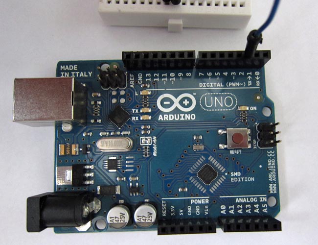 Step 12
 Attach +5v jumper (orange) to 5v on Arduino.
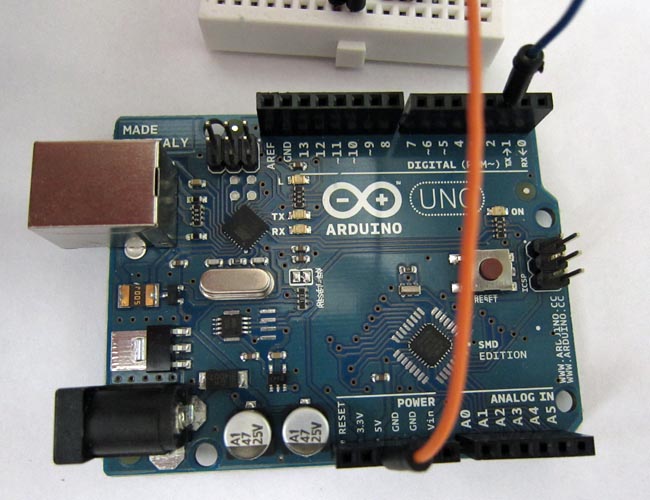 Step 13
 Attach gnd jumper (green) to GND on Arduino.
 Step 14
 Attach jumper wires to the rails where a DCC signal will be present. The rails are not shown in photo but they're on the other end of the clip leads. We tested this with our NCE system.
 Software
Step 15
Software
Step 15 Download and install our DCC_Decoder library. The download is in a zip file. In general, you'll unzip this to get the DCC_Decoder directory. Copy this directory to the libraries directory inside the sketchbook location. The libraries directory may not exist and you'll need to create one. See the preferences in the Arduino IDE for the sketchbook directory location. Place the DCC_Decoder directory (not .zip file, it's unzipped contents) inside the directory named libraries.
See the Arduino site for more information on installing a library.
dcc_decoder.v4.zip
Step 16 Attach the Arduino to your platform with the USB cable. No photo, but a simple step.
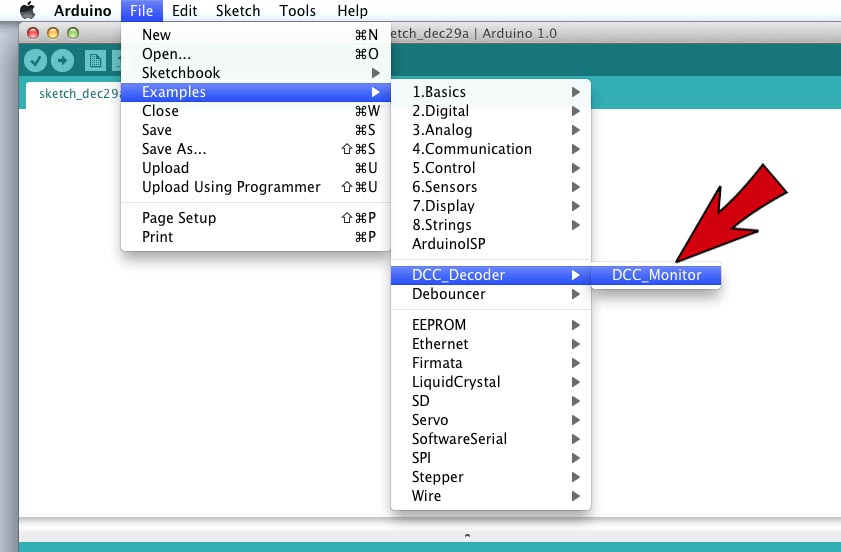
Step 17 Launch Arduino IDE and choose the DCC_Monitor example. If DCC_Decoder isn't there you might need to restart Arduino IDE or the library isn't installed correctly. Go back to step 15.
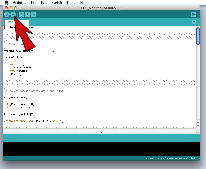
 Step 18
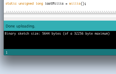
 Upload the sketch to your Adruino.
 Step 19
 Wait for upload to finish.
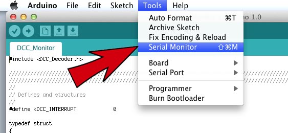
 Step 20
 Open the Serial Monitor in the Arduino IDE.
 Step 21
 Turn on the DCC booster and watch packet data in monitor window.
Ref: http://www.mynabay.com/