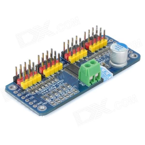
16-Channel Servo Motor Controller / PWM Servo Driver Board
-
This is a i2c-controlled PWM driver board with a built-in clock, which is quite different from TLC5940 series. You don’t need to continuously send signals and occupy your MCU.
-
5V compatibility, which means that you can use 3.3V MCU to control and drive the output up to 6V (when you want to control the white or blue indicator light, 3.4V+ is also OK).
-
6 address select pins allow you to connect 62 driver boards to one i2C bus, total 992 channels of PWM output.
-
About 1.6KHz frequency modulation PWM output.
-
Get 12-bit resolution output ready for stepping motor, which means that the 60Hz update rate can reach to 4us resolution.
-
Configurable totem-pole output or open-collector output.
-
Output enable pin can quick disable all outputs.
-
PCA9685 chip is at the center of the board.
-
With power input terminal.
-
With green power indicator light.
-
Convenient to insert total 16 servos at the same time (the plug of servo is a little large than 0.1", so you can put 4 pairs of 0.1" connectors).
-
With reverse polarity protection for input.
-
Cascade design.
-
Put a bulky capacitor on the V+ line (sometimes you need it).
-
Put 220 ohm resistance components onto all PWM output lines, so as to protect them, and you can easily drive the LED.
Hooking it Up
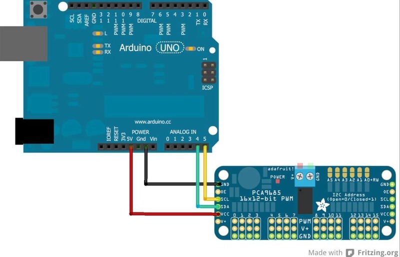
Connecting to the Arduino
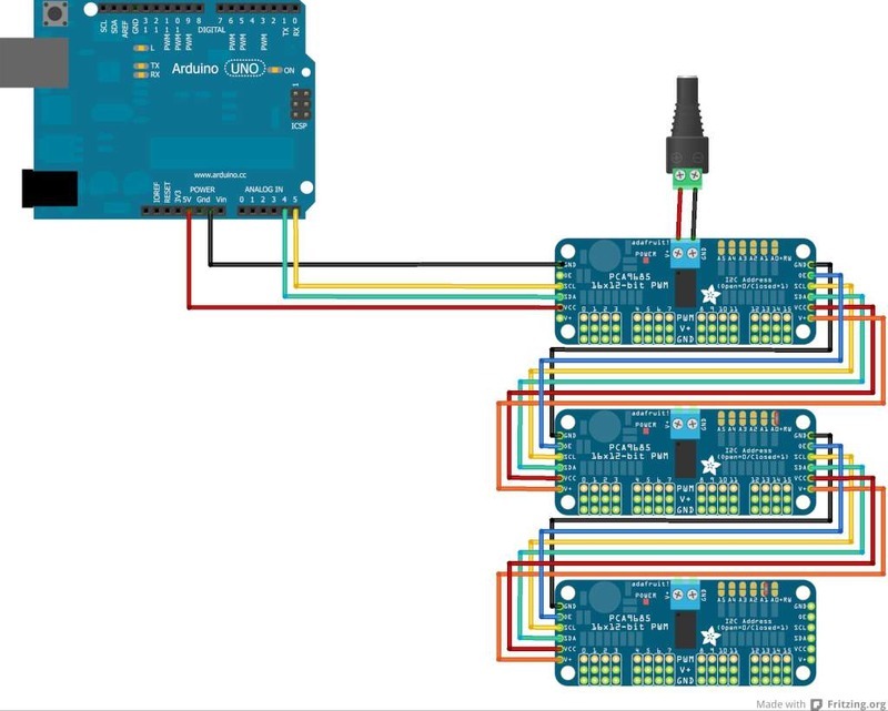
The PWM/Servo Driver uses I2C so it take only 4 wires to connect to your Arduino:
"Classic" Arduino wiring:
-
- +5v -> VCC (this is power for the BREAKOUT only, NOT the servo power!)
- GND -> GND
- Analog 4 -> SDA
- Analog 5 -> SCL
Older Mega wiring:
- +5v -> VCC (this is power for the BREAKOUT only, NOT the servo power!)
- GND -> GND
- Digital 20 -> SDA
- Digital 21 -> SCL
R3 and later Arduino wiring (Uno, Mega & Leonardo):
(These boards have dedicated SDA & SCL pins on the header nearest the USB connector)
- +5v -> VCC (this is power for the BREAKOUT only, NOT the servo power!)
- GND -> GND
- SDA -> SDA
- SCL -> SCL
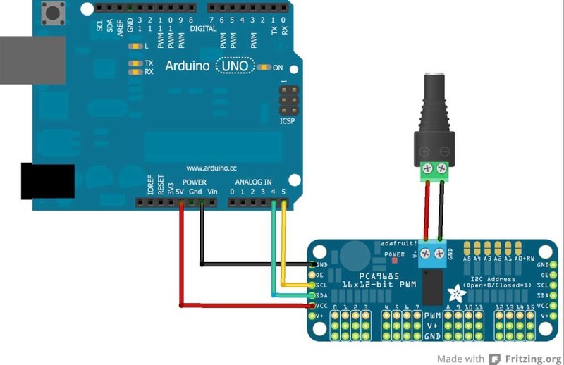
The VCC pin is just power for the chip itself. If you want to connect servos or LEDs that use the V+ pins, you MUST connect the V+ pin as well. The V+ pin can be as high as 6V even if VCC is 3.3V (the chip is 5V safe). We suggest connecting power through the blue terminal block since it is polarity protected.
Power for the Servos/LEDs
Most servos are designed to run on about 5 or 6v. Keep in mind that a lot of servos moving at the same time (particularly large powerful ones) will need a lot of current. Even micro servos will draw several hundred mA when moving. Some High-torque servos will draw more than 1A each under load.
Good power choices are:
-
- 5v 2A switching power supply
- 5v 10A switching power supply
- 4xAA Battery Holder - 6v with Alkaline cells. 4.8v with NiMH rechargeable cells.
- 4.8 or 6v Rechargeable RC battery packs from a hobby store.
It is not a good idea to use the Arduino 5v pin to power your servos. Electrical noise and 'brownouts' from excess current draw can cause your Arduino to act erratically, reset and/or overheat.
Adding a Capacitor to the thru-hole capacitor slot
We have a spot on the PCB for soldering in an electrolytic capacitor. Based on your usage, you may or may not need a capacitor. If you are driving a lot of servos from a power supply that dips a lot when the servos move, n * 100uF where n is the number of servos is a good place to start - eg 470uF or more for 5 servos. Since its so dependent on servo current draw, the torque on each motor, and what power supply, there is no "one magic capacitor value" we can suggest which is why we don't include a capacitor in the kit.
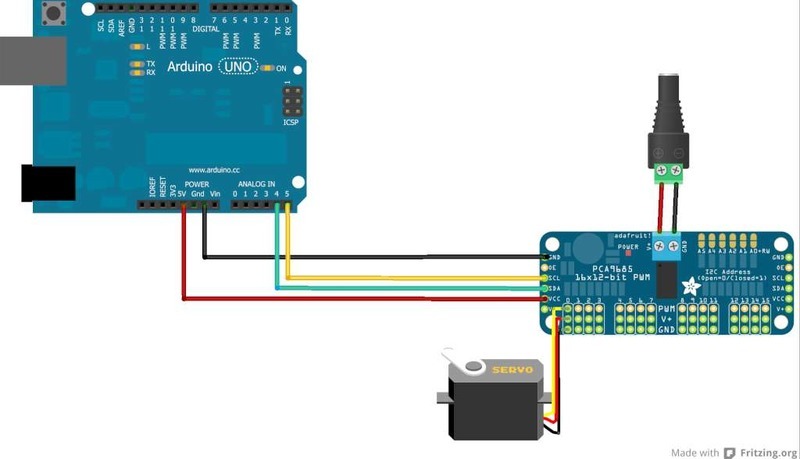
Connecting a Servo
Most servos come with a standard 3-pin female connector that will plug directly into the headers on the Servo Driver. Be sure to align the plug with the ground wire (usually black or brown) with the bottom row and the signal wire (usually yellow or white) on the top.
Chaining Drivers
Multiple Drivers (up to 62) can be chained to control still more servos. With headers at both ends of the board, the wiring is as simple as connecting a 6-pin parallel cable from one board to the next.
Addressing the Boards
Each board in the chain must be assigned a unique address. This is done with the address jumpers on the upper right edge of the board. The I2C base address for each board is 0x40. The binary address that you program with the address jumpers is added to the base I2C address.
To program the address offset, use a drop of solder to bridge the corresponding address jumper for each binary '1' in the address.
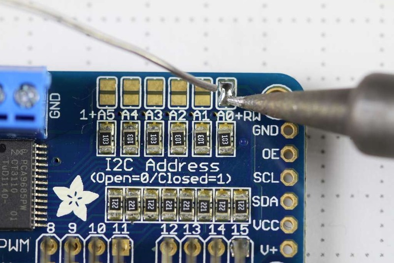
Board 0: Address = 0x40 Offset = binary 00000 (no jumpers required)
Board 1: Address = 0x41 Offset = binary 00001 (bridge A0 as in the photo above)
Board 2: Address = 0x42 Offset = binary 00010 (bridge A1)
Board 3: Address = 0x43 Offset = binary 00011 (bridge A0 & A1)
Board 4: Address = 0x44 Offset = binary 00100 (bridge A2)
etc.
In your sketch, you'll need to declare a separate pobject for each board. Call begin on each object, and control each servo through the object it's attached to. For example:
#include
#include

Adafruit_PWMServoDriver pwm1 = Adafruit_PWMServoDriver(0x40);
Adafruit_PWMServoDriver pwm2 = Adafruit_PWMServoDriver(0x41);

void setup() {
  Serial.begin(9600);
  Serial.println("16 channel PWM test!");

  pwm1.begin();
  pwm1.setPWMFreq(1600);  // This is the maximum PWM frequency

  pwm2.begin();
  pwm2.setPWMFreq(1600);  // This is the maximum PWM frequency
}
Library Adafruit
Adafruit-PWM-Servo-Driver-Library-master
Copy the zip file to the Libraries folder inside your Arduino Sketchbook folder and re-name it to Adafruit_PWMServoDriver.
Test with the Example Code:
First make sure all copies of the Arduino are closed.
Next open a new copy of the IDE and select "File->Examples->Adafruit_PWMServoDriver->Servo". This will open the example file in an IDE window.
Connect the driver board and servo as shown on the previous page and upload the example code.
You should see the servo sweep back and forth over approximately 180 degrees.
Calibrating your Servos
Servo pulse timing varies between different brands and models. Since it is an analog control circuit, there is often some variation between samples of the same brand and model. For precise position control, you will want to calibrate the minumum and maximum pulse-widths in your code to match known positions of the servo.
Find the Minimum:
Using the example code, edit SERVOMIN until the low-point of the sweep reaches the minimum range of travel. It is best to approach this gradually and stop before the physical limit of travel is reached.
Find the Maximum:
Again using the example code, edit SERVOMAX until the high-point of the sweep reaches the maximum range of travel. Again, is best to approach this gradually and stop before the physical limit of travel is reached.
Use caution when adjusting SERVOMIN and SERVOMAX. Hitting the physical limits of travel can strip the gears and permanently damage your servo.
Converting from Degrees to Pulse Length
The Arduino "map()" function is an easy way to convert between degrees of rotation and your calibrated SERVOMIN and SERVOMAX pulse lengths. Assuming a typical servo with 180 degrees of rotation; once you have calibrated SERVOMIN to the 0-degree position and SERVOMAX to the 180 degree position, you can convert any angle between 0 and 180 degrees to the corresponding pulse length with the following line of code:
pulselength = map(degrees, 0, 180, SERVOMIN, SERVOMAX);
Library Reference
setPWMFreq(freq)
Description
This function can be used to adjust the PWM frequency, which determines how many full 'pulses' per second are generated by the IC. Stated differently, the frequency determines how 'long' each pulse is in duration from start to finish, taking into account both the high and low segments of the pulse.
Frequency is important in PWM, since setting the frequency too high with a very small duty cycle can cause problems, since the 'rise time' of the signal (the time it takes to go from 0V to VCC) may be longer than the time the signal is active, and the PWM output will appear smoothed out and may not even reach VCC, potentially causing a number of problems.
Arguments
freq: A number representing the frequency in Hz, between 40 and 1000
Example
The following code will set the PWM frequency to the maximum value of 1000Hz:
pwm.setPWMFreq(1000)
setPWM(channel, on, off)
Description
This function sets the start (on) and end (off) of the high segment of the PWM pulse on a specific channel. You specify the 'tick' value between 0..4095 when the signal will turn on, and when it will turn of. Channel indicates which of the 16 PWM outputs should be updated with the new values.
Arguments
channel: The channel that should be updated with the new values (0..15)
on: The tick (between 0..4095) when the signal should transition from low to high
off:the tick (between 0..4095) when the signal should transition from high to low
Example
The following example will cause channel 15 to start low, go high around 25% into the pulse (tick 1024 out of 4096), transition back to low 75% into the pulse (tick 3072), and remain low for the last 25% of the pulse:
pwm.setPWM(15, 1024, 3072)
Library PCA9685
ref:
dx.com
adafruit.com
|