WeMos SAMD21 M0
The Seeed Studio XIAO SAMD21 is the smallest member of the Seeeduino family. It carries the powerful ATSAMD21G18A-MU which is a low-power microcontrollers. On the other hand, this little board has good performance in processing but needs less power. As a matter of fact, it is designed in a tiny size and can be used for wearable devices and small projects.
Seeed Studio XIAO SAMD21 has 14 PINs, which can be used for 11 digital interfaces, 11 mock interfaces, 10 PWM interfaces (d1-d10), 1 DAC output pin D0, 1 SWD pad interface, 1 I2C interface, 1 SPI interface, 1 UART interface, Serial communication indicator (T/R), Blink light (L) through pin multiplexing. The colors of LEDs(Power,L,RX,TX) are green, yellow, blue and blue. Moreover, Seeed Studio XIAO SAMD21 has a Type-C interface which can supply power and download code. There are two reset button, you can short connect them to reset the board.
Features
- Powerful CPU: ARM® Cortex®-M0+ 32bit 48MHz microcontroller(SAMD21G18) with 256KB Flash,32KB SRAM.
- Flexible compatibility: Compatible with Arduino IDE.
- Easy project operation: Breadboard-friendly.
- Small size: As small as a thumb(20x17.5mm) for wearable devices and small projects.
- Multiple development interfaces: 11 digital/analog pins, 10 PWM Pins, 1 DAC output, 1 SWD Bonding pad interface, 1 I2C interface, 1 UART interface, 1 SPI interface.
Specification
| CPU | ARM Cortex-M0+ CPU(SAMD21G18) running at up to 48MHz |
| Flash Memory | 256KB |
| SRAM | 32KB |
| Digital I/O Pins | 11 |
| Analog I/O Pins | 11 |
| I2C interface | 1 |
| SPI interface | 1 |
| QTouch | 7 (A0,A1,A6,A7,A8,A9,A10) |
| UART interface | 1 |
| Power supply and downloading interface | Type-C |
| Power | 3.3V/5V DC |
| Dimensions | 20×17.5×3.5mm |
Pin
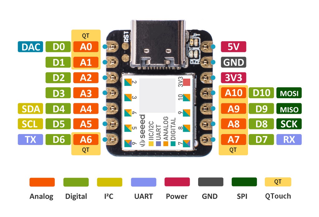
Working voltage of MCU is 3.3V . Voltage input connected to general I/O pins may cause chip damage if it' higher than 3.3V .
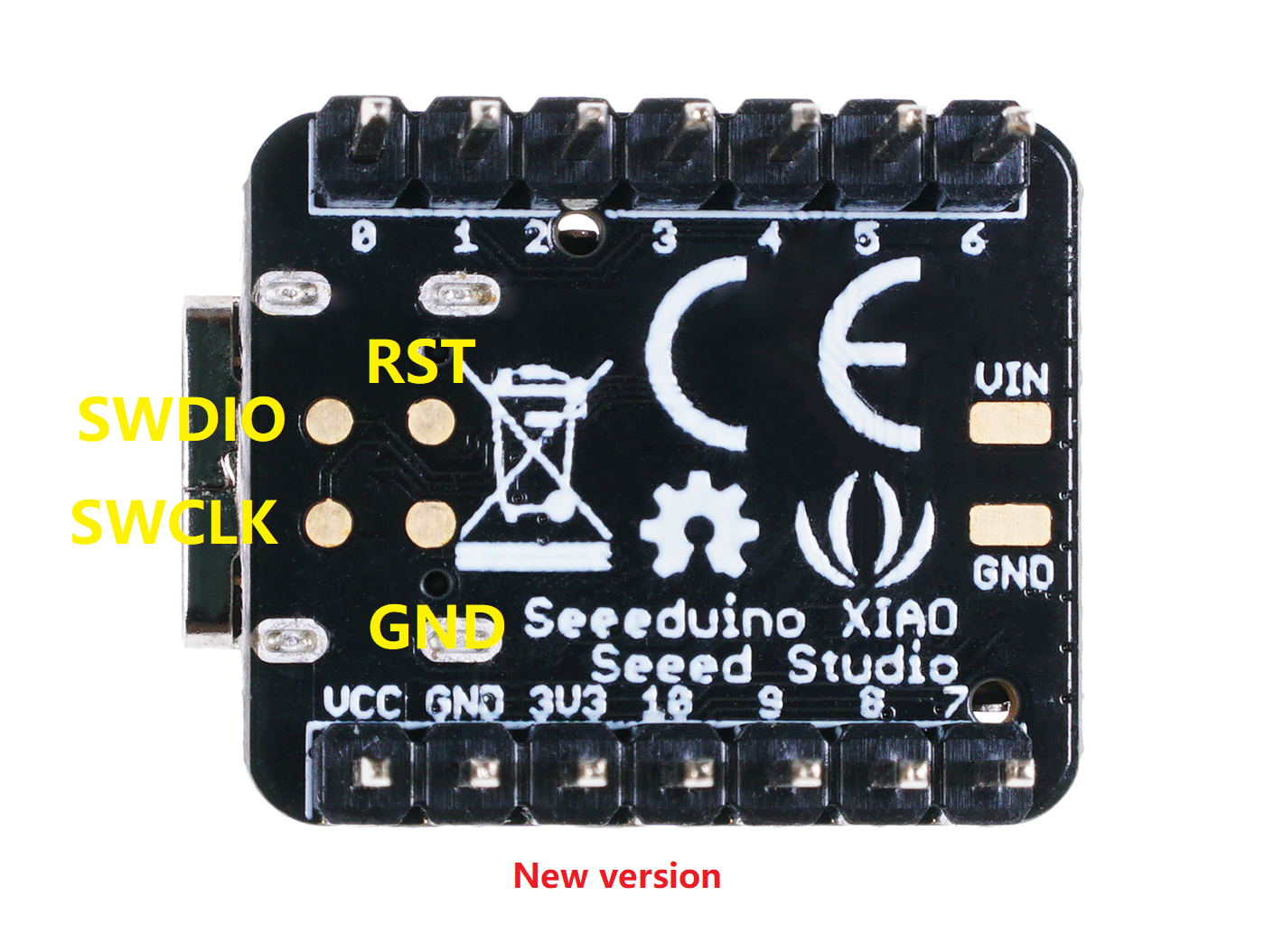
For power supply pins:
The built-in DC-DC converter circuit able to change 5V voltage into 3.3V allows to power the device with a 5V supply via VIN-PIN and 5V-PIN.
Enter Bootloader Mode
Sometimes the Seeed Studio XIAO SAMD21 port may disappear when user programming process fails. we can solve this problem by the following operation:
- Connect the Seeed Studio XIAO SAMD21 to your computer.
- Use tweezers or short lines to short the RST pins in the diagram twice.
- The orange LED lights flicker on and light up.
At this point, the chip enters Bootloader mode and the burn port appears again. Because the samd21 chip has two partitions, one is the Bootloader and the other is the user program. The product will burn a bootloader code in the system memory when it leaves the factory. We can switch modes by performing the above steps.
Reset
If you want to reset the Seeed Studio XIAO SAMD21 , perform the following steps:
- Connect the Seeed Studio XIAO SAMD21 to your computer.
- Use tweezers or short lines to short the RST pins only once
- The orange LED lights flicker on and light up.
Please note: The behavior of the built-in LED is reversed to the one on an Arduino. On the Seeed Studio XIAO SAMD21 , the pin has to be pulled low, whereas on other micro-controllers it has to be pulled high.
Interrupt
All pins on Seeed Studio XIAO SAMD21 support interrupts, but two pins cannot be used at the same time: 5 pin and 7 pin.
/*
  Copyright (c) 2014-2015 Arduino LLC.  All right reserved.
  This library is free software; you can redistribute it and/or
  modify it under the terms of the GNU Lesser General Public
  License as published by the Free Software Foundation; either
  version 2.1 of the License, or (at your option) any later version.
  This library is distributed in the hope that it will be useful,
  but WITHOUT ANY WARRANTY; without even the implied warranty of
  MERCHANTABILITY or FITNESS FOR A PARTICULAR PURPOSE.
  See the GNU Lesser General Public License for more details.
  You should have received a copy of the GNU Lesser General Public
  License along with this library; if not, write to the Free Software
  Foundation, Inc., 51 Franklin St, Fifth Floor, Boston, MA  02110-1301  USA
*/

#include "variant.h"

/*
 * Pins descriptions
 */
const PinDescription g_APinDescription[]=
{
  // 0..10 - Digitabl & Analog pins
  { PORTA,  2, PIO_ANALOG, PIN_ATTR_ANALOG, ADC_Channel0, NOT_ON_PWM, NOT_ON_TIMER, EXTERNAL_INT_2 }, // ADC/AIN[0]
  { PORTA,  4, PIO_ANALOG, (PIN_ATTR_PWM|PIN_ATTR_TIMER), ADC_Channel4, PWM0_CH0, TCC0_CH0, EXTERNAL_INT_4 }, // ADC/AIN[4]
  { PORTA, 10, PIO_ANALOG, (PIN_ATTR_DIGITAL|PIN_ATTR_PWM|PIN_ATTR_TIMER_ALT), ADC_Channel18, PWM0_CH2, TCC0_CH2, EXTERNAL_INT_10 },
  { PORTA, 11, PIO_ANALOG, (PIN_ATTR_DIGITAL|PIN_ATTR_PWM|PIN_ATTR_TIMER_ALT), ADC_Channel19, PWM0_CH3, TCC0_CH3, EXTERNAL_INT_11 },
  // 4..5 - I2C SERCOM2
  { PORTA,  8, PIO_SERCOM_ALT, (PIN_ATTR_DIGITAL|PIN_ATTR_PWM|PIN_ATTR_TIMER_ALT), ADC_Channel16, PWM1_CH2, TCC1_CH2, EXTERNAL_INT_NMI },  // SDA: SERCOM2/PAD[0]
  { PORTA,  9, PIO_SERCOM_ALT, (PIN_ATTR_DIGITAL|PIN_ATTR_PWM|PIN_ATTR_TIMER_ALT), ADC_Channel17, PWM1_CH3, TCC1_CH3, EXTERNAL_INT_9 }, // SCL: SERCOM2/PAD[1]
  // 6..7 - UART SERCOM4
  { PORTB,  8, PIO_SERCOM_ALT, (PIN_ATTR_PWM|PIN_ATTR_TIMER), ADC_Channel2, PWM4_CH0, TC4_CH0, EXTERNAL_INT_8 }, // TX: SERCOM4/PAD[0]
  { PORTB,  9, PIO_SERCOM_ALT, (PIN_ATTR_PWM|PIN_ATTR_TIMER), ADC_Channel3, PWM4_CH1, TC4_CH1, EXTERNAL_INT_9 }, // RX: SERCOM4/PAD[1]

  // 8..10 - SPI SERCOM0
  { PORTA,  7, PIO_SERCOM_ALT, (PIN_ATTR_DIGITAL|PIN_ATTR_PWM|PIN_ATTR_TIMER), ADC_Channel7, PWM1_CH1, TCC1_CH1, EXTERNAL_INT_7 }, // SCK: SERCOM0/PAD[3]
  { PORTA,  5, PIO_SERCOM_ALT, (PIN_ATTR_PWM|PIN_ATTR_TIMER), ADC_Channel5, PWM0_CH1, TCC0_CH1, EXTERNAL_INT_5 }, // MISO: SERCOM0/PAD[1]
  { PORTA,  6, PIO_SERCOM_ALT, (PIN_ATTR_DIGITAL|PIN_ATTR_PWM|PIN_ATTR_TIMER), ADC_Channel6, PWM1_CH0, TCC1_CH0, EXTERNAL_INT_6 }, // MOSI: SERCOM0/PAD[2]

  // 11..13 - LED
  { PORTA, 19, PIO_TIMER, (PIN_ATTR_DIGITAL|PIN_ATTR_PWM|PIN_ATTR_TIMER), No_ADC_Channel, PWM3_CH1, TC3_CH1, EXTERNAL_INT_3 }, // TCC0/WO[3]
  { PORTA, 18, PIO_TIMER, (PIN_ATTR_DIGITAL|PIN_ATTR_PWM|PIN_ATTR_TIMER), No_ADC_Channel, PWM3_CH0, TC3_CH0, EXTERNAL_INT_2 }, // TC3/WO[0]
  { PORTA, 17, PIO_PWM, (PIN_ATTR_DIGITAL|PIN_ATTR_PWM|PIN_ATTR_TIMER), No_ADC_Channel, PWM2_CH1, TCC2_CH1, EXTERNAL_INT_1 }, // TCC2/WO[1]

  // 14..16 - USB
  // --------------------
  { PORTA, 28, PIO_COM, PIN_ATTR_NONE, No_ADC_Channel, NOT_ON_PWM, NOT_ON_TIMER, EXTERNAL_INT_NONE }, // USB Host enable
  { PORTA, 24, PIO_COM, PIN_ATTR_NONE, No_ADC_Channel, NOT_ON_PWM, NOT_ON_TIMER, EXTERNAL_INT_NONE }, // USB/DM
  { PORTA, 25, PIO_COM, PIN_ATTR_NONE, No_ADC_Channel, NOT_ON_PWM, NOT_ON_TIMER, EXTERNAL_INT_NONE } // USB/DP

} ;

const void* g_apTCInstances[TCC_INST_NUM+TC_INST_NUM]={ TCC0, TCC1, TCC2, TC3, TC4, TC5 } ;

// Multi-serial objects instantiation
SERCOM sercom0( SERCOM0 ) ;
SERCOM sercom1( SERCOM1 ) ;
SERCOM sercom2( SERCOM2 ) ;
SERCOM sercom3( SERCOM3 ) ;
SERCOM sercom4( SERCOM4 ) ;
SERCOM sercom5( SERCOM5 ) ;

#ifndef NO_USART_INTERFACE

Uart Serial1( &sercom4, PIN_SERIAL1_RX, PIN_SERIAL1_TX, PAD_SERIAL1_RX, PAD_SERIAL1_TX ) ;

void SERCOM4_Handler()
{
  Serial1.IrqHandler();
}

#endif
Pin Multuiplexing
We don't need to configure the pins ourselves, after using the pins, you can call a function directly.
Digital Input and Output
Use pin 6 as the digital pin:
const int buttonPin = 6;     // the number of the pushbutton pin
const int ledPin =  13;      // the number of the LED pin

int buttonState = 0;         // variable for reading the pushbutton status

void setup() {
  // initialize the LED pin as an output:
  pinMode(ledPin, OUTPUT);
  // initialize the pushbutton pin as an input:
  pinMode(buttonPin, INPUT);
}

void loop() {
  // read the state of the pushbutton value:
  buttonState = digitalRead(buttonPin);

  // check if the pushbutton is pressed. If it is, the buttonState is HIGH:
  if (buttonState == HIGH) {
    // turn LED on:
    digitalWrite(ledPin, HIGH);
  } else {
    // turn LED off:
    digitalWrite(ledPin, LOW);
  }
}
AnalogRead
Use pin 6 as the analog pin:
void setup() {
  // declare the ledPin as an OUTPUT:
  pinMode(ledPin, OUTPUT);
}

void loop() {
  // read the value from the sensor:
  sensorValue = analogRead(sensorPin);
  // turn the ledPin on
  digitalWrite(ledPin, HIGH);
  // stop the program for  milliseconds:
  delay(sensorValue);
  // turn the ledPin off:
  digitalWrite(ledPin, LOW);
  // stop the program for for  milliseconds:
  delay(sensorValue);
}
Serial
Use pin 6 as the TX pin of UART(RX pin of UART is pin 7):
void setup() {
    Serial1.begin(115200);
    while (!Serial);
}

void loop() {
    Serial1.println("Hello,World");
    delay(1000);
}
I2C
Use pin 5 as the SCL pin of IIC(SDA pin of IIC is pin 4):
// Demonstrates use of the Wire library
// Writes data to an I2C/TWI slave device
// Refer to the "Wire Slave Receiver" example for use with this

// Created 29 March 2006

// This example code is in the public domain.


#include

void setup()
{
  Wire.begin(); // join i2c bus (address optional for master)
}

byte x = 0;

void loop()
{
  Wire.beginTransmission(4); // transmit to device #4
  Wire.write("x is ");        // sends five bytes
  Wire.write(x);              // sends one byte
  Wire.endTransmission();    // stop transmitting
  x++;
  delay(500);
}
SPI
Use pin 8 as the SCK pin of SPI(MISO pin of SPI is pin 9,MOSI pin of SPI is pin 10):
#include
const int CS = 7;
void setup (void) {
   digitalWrite(CS, HIGH); // disable Slave Select
   SPI.begin ();
   SPI.setClockDivider(SPI_CLOCK_DIV8);//divide the clock by 8
}

void loop (void) {
   char c;
   digitalWrite(CS, LOW); // enable Slave Select
   // send test string
   for (const char * p = "Hello, world!\r" ; c = *p; p++) {
      SPI.transfer (c);
   }
   digitalWrite(CS, HIGH); // disable Slave Select
   delay(2000);
}
Use arduino ide
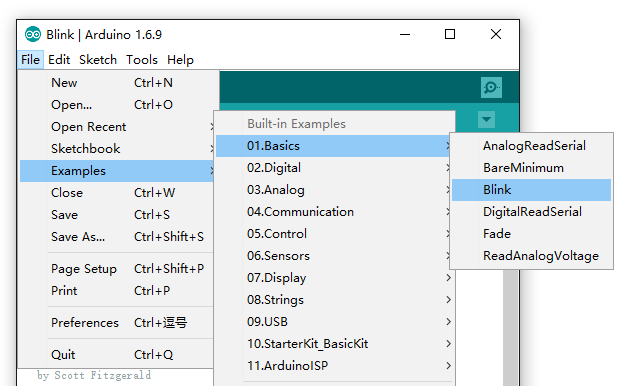
Open the Blink example
Open the LED blink example sketch: File > Examples >01.Basics > Blink.
Add Seeeduino to your Arduino IDE
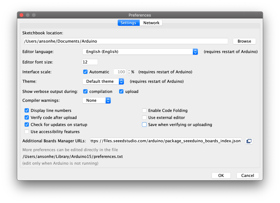
Click on File > Preference, and fill Additional Boards Manager URLs with the url below:
https://files.seeedstudio.com/arduino/package_seeeduino_boards_index.json
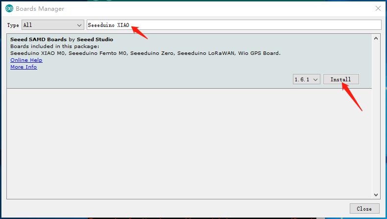
Click Tools-> Board-> Boards Manager..., print keyword "Seeed Studio XIAO SAMD21" in the searching blank. Here comes the "Seeed SAMD Boards". Install it.
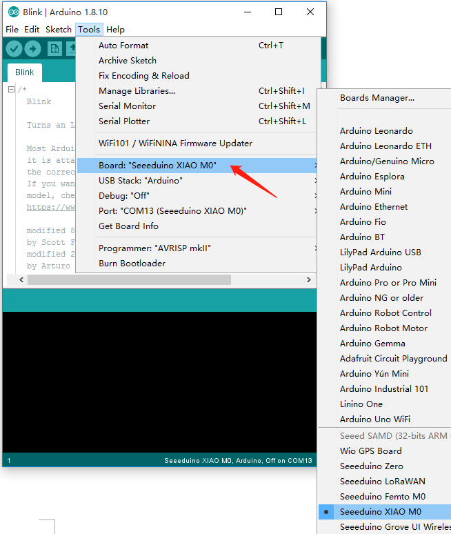
After installing the board, click Tools-> Board, find "Seeed Studio XIAO SAMD21 M0" and select it. Now you have already set up the board of Seeed Studio XIAO SAMD21 for Arduino IDE.
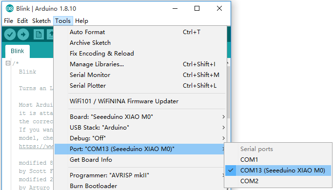
Select the serial device of the Arduino board from the Tools | Serial Port menu. This is likely to be COM3 or higher (COM1 and COM2 are usually reserved for hardware serial ports). To find out, you can disconnect your Arduino board and re-open the menu; the entry that disappears should be the Arduino board. Reconnect the board and select that serial port.
Now, simply click the "Upload" button in the environment. Wait a few seconds and if the upload is successful, the message "Done uploading." will appear in the status bar.
A few seconds after the upload finishes, you should see the pin 13 (L) LED on the board start to blink (in orange). If it does, congratulations! You've gotten Arduino up-and-running.
#1, Bak 4.02