WeMos SAMD21 M0
How to program the WeMos or RobotDyn Arduino M0 SAMD21 clone/variant using the Arduino IDE software in this WeMos SAMD21 Arduino M0.
Set up the WeMos or RobotDyn Arduino M0 compatible board in the Arduino IDE. Program the on-board LED and Serial/SerialUSB ports.
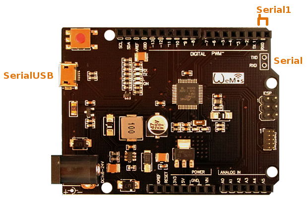
Apparently this board (shown below) which is marked WeMos is not produced by WeMos, but has the WeMos logo silk-screened on the board. The same board is also sold with RobotDyn SAMD21M0 silk-screened on the board. It is not a direct clone of an Arduino M0, but has a few modifications such as the extra TXD and RXD pins at the end of the board. Therefore it can be considered a variant of the Arduino M0, rather than a clone (a clone would be an exact copy).
Install Arduino M0 Tools in the Arduino IDE
To install the Arduino M0 programming tools, open the Arduino IDE and then select Tools → Board → Boards Manager... from the top menu. In the Boards Manager dialog box, type M0 in the search or filter field. Click Arduino SAMD Boards (32-bits ARM Cortex-M0+) by Arduino in the filtered list and then the Install button that appears on the selected item to start the installation.
Select the WeMos M0 Board in the Arduino IDE
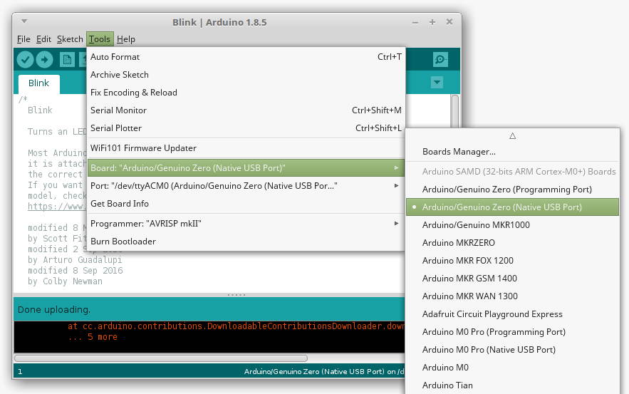
The WeMos SAMD21 M0 is programmed with the Arduino Zero bootloader and not the Arduino M0 bootloader. This means that the board must be configured as Arduino/Genuino Zero (Native USB Port) in the Arduino IDE. I have not tested the RobotDyn board to confirm that it is using the same bootloader.
From the top Arduino IDE menu, select Tools → Board → Arduino/Genuino Zero (Native USB Port) as shown in the image below. Select the correct serial port under Tools → Port also from the top menu.
Programming the On-board LED
With the correct board and port selected as described above, the blink example sketch from the IDE can be loaded to the board to blink the on-board L LED.
In the Arduino IDE, open the blink sketch from the top menu under File → Examples → 01.Basics → Blink and load it to the WeMos M0 board.
If the correct board and port is selected and the board is working, the L LED will start blinking.
Programming the Serial Ports
Unlike Arduino boards such as the Arduino Uno or even an Arduino M0 Pro using the Programming port, the Arduino M0 or WeMos variant does not feed the default serial port into a chip on the board that controls the USB programming. This means that programs or sketches that use the default Serial port will not work through the USB connection. The USB connection on Arduino M0 and compatible boards is the native USB connection of the main microcontroller on the board.
What the above means is that all software that uses the Serial object must be changed to use the SerialUSB object instead. Alternatively a USB to 3.3V TTL device such as those based on the FTDI chip can be used to connect to one of the other serial ports on the board. If a USB to TTL converter is used, then an external serial program, such as Tera Term on Windows or minicom on Linux, will need to be used instead of the Arduino IDE Serial Monitor.
The image below shows how the serial ports on the WeMos SAMD21 M0 map to serial port objects in software, an explanation of each port follows.
SerialUSB
The SerialUSB object is used to send and receive serial data over the USB link, e.g. to the Arduino IDE Serial Monitor window. Sketches that normally use the Serial Monitor window with other Arduino boards must be modified to use SerialUSB when using Arduino M0 compatible boards
SerialUSB example code:
SerialUSB.begin(9600);
while (!SerialUSB);
SerialUSB.println("Test SerialUSB");
Serial
The Serial object in a sketch uses the TXD and RXD pins at the end of the board as shown in the above image. A USB to TTL (3.3V) converter cable can be used to connect to this port. When a converter is used, TX or TXD (transmit) of the converter connects to RX or RXD (receive) on the Arduino. RX or RXD of the converter connects to TX or TXD on the Arduino.
Serial example code:
Serial.begin(9600);
while (!Serial);
Serial.println("Test Serial");
Serial1
Digital pins 0 and 1 connect to RX and TX serial port pins. The Serial1 object in a sketch uses these pins. The same USB to TTL converter as described above can be used on these pins.
Serial1 example code:
Serial1.begin(9600);
while (!Serial1);
Serial1.println("Test Serial1");
WeMos SAMD21 M0 Serial Port Sketch
The above code snippets are shown below in an Arduino sketch.
                // Serial Ports on the WeMos M0 (Arduino M0 variant)
                // https://startinglectronics.org/articles/arduino/wemos-arduino-m0/
                // 30 May 2018 | W.A. Smith

                void setup() {
                  // Virtual USB COM Port (Native USB)
                  SerialUSB.begin(9600);
                  while (!SerialUSB);
                  SerialUSB.println("Test SerialUSB");

                  // TXD and RXD pins at end of board
                  Serial.begin(9600);
                  while (!Serial);
                  Serial.println("Test Serial");

                  // TX and RX pins on digital pins 0 and 1
                  Serial1.begin(9600);
                  while (!Serial1);
                  Serial1.println("Test Serial1");
                }

                void loop() {
                  // Square wave for oscilloscope testing
                  //Serial.write('U');
                }
The above code was tested using a USB to TTL converter and external terminal program. Sending a capital 'U', as shown in the commented out code in loop() produces a square wave on TX or TXD pin of the Arduino that can be tested with an oscilloscope. This works on Serial or Serial1.
#1, Bak 4.02