STM32F103C8T6
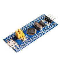
The STM32F103xx medium-density performance line family incorporates the highperformance ARM® Cortex®-M3 32-bit RISC core operating at a 72 MHz frequency, highspeed embedded memories (Flash memory up to 128 Kbytes and SRAM up to 20 Kbytes), and an extensive range of enhanced I/Os and peripherals connected to two APB buses. All devices offer two 12-bit ADCs, three general purpose 16-bit timers plus one PWM timer, as well as standard and advanced communication interfaces: up to two I2Cs and SPIs, three USARTs, an USB and a CAN.
The devices operate from a 2.0 to 3.6 V power supply. They are available in both the –40 to +85 °C temperature range and the –40 to +105 °C extended temperature range. A comprehensive set of power-saving mode allows the design of low-power applications. The STM32F103xx medium-density performance line family includes devices in six different package types: from 36 pins to 100 pins. Depending on the device chosen, different sets of peripherals are included, the description below gives an overview of the complete range of peripherals proposed in this family. These features make the STM32F103xx medium-density performance line microcontroller family suitable for a wide range of applications such as motor drives, application control, medical and handheld equipment, PC and gaming peripherals, GPS platforms, industrial applications, PLCs, inverters, printers, scanners, alarm systems, video intercoms, and HVACs.
Features
ARM® 32-bit Cortex®-M3 CPU Core
- 72 MHz maximum frequency, 1.25 DMIPS/MHz (Dhrystone 2.1) performance at 0 wait state memory access
- Single-cycle multiplication and hardware division
Memories
- 64 or 128 Kbytes of Flash memory
- 20 Kbytes of SRAM
Clock, reset and supply management
- 2.0 to 3.6 V application supply and I/Os
- POR, PDR, and programmable voltage
detector (PVD)
- 4-to-16 MHz crystal oscillator
- Internal 8 MHz factory-trimmed RC
- Internal 40 kHz RC
- PLL for CPU clock
- 32 kHz oscillator for RTC with calibration
Low-power
- Sleep, Stop and Standby modes
- VBAT supply for RTC and backup registers
2 x 12-bit, 1 µs A/D converters (up to 16 channels)
- Conversion range: 0 to 3.6 V
- Dual-sample and hold capability
- Temperature sensor
DMA
- 7-channel DMA controller
- Peripherals supported: timers, ADC, SPIs, I2Cs and USARTs
Up to 80 fast I/O ports
- 26/37/51/80 I/Os, all mappable on 16 external interrupt vectors and almost all 5 V-tolerant
Debug mode
- Serial wire debug (SWD) & JTAG interfaces
7 timers
- Three 16-bit timers, each with up to 4 IC/OC/PWM or pulse counter and quadrature (incremental) encoder input
- 16-bit, motor control PWM timer with deadtime generation and emergency stop
- 2 watchdog timers (Independent and Window)
- SysTick timer 24-bit downcounter
Up to 9 communication interfaces
- Up to 2 x I2C interfaces (SMBus/PMBus)
- Up to 3 USARTs (ISO 7816 interface, LIN, IrDA capability, modem control)
- Up to 2 SPIs (18 Mbit/s)
- CAN interface (2.0B Active)
- USB 2.0 full-speed interface
 Datasheet
Generic STM32 board with Arduino
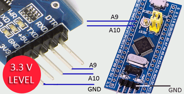
Described here is a simple way to load a program without bootloader. An additional thing needed is a USB to Serial/UART/TTL adapter (3.3V level). Connect the USB to Serial board as follows, and power up the STM32 board from a USB port/power supply.
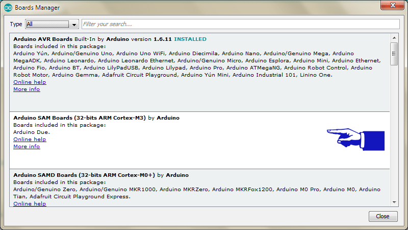
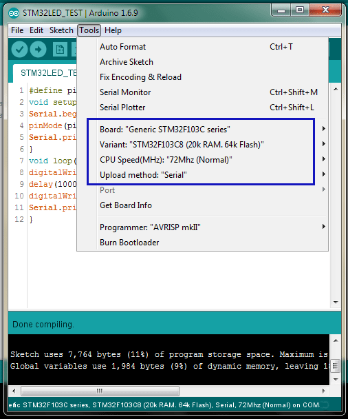
I assume you have already installed the Arduino IDE. Next, you need to go to ‘Board Manager’ under ‘Tools’ and install the support for SAM boards. Download the necessary files as well as the “Arduino_STM32’ (from the link). Extract “Arduino_STM32’ and copy the folder ‘Arduino_STM32-master’ to your Arduino ‘Hardware’ folder. Finally, restart the Arduino IDE, choose correct board settings, compile the given sketch, and upload it. Before uploading, set the onboard ‘BOOT0’ jumper to 1, and press ‘reset’ button. After upload completed, the sketch will run. If you want the uploaded sketch to run automatically after next power on/reset, set ‘BOOT0‘ jumper back to 0.
[stextbox id=”grey”]
#define pinLED PC13
void setup() {
Serial.begin(9600);
pinMode(pinLED, OUTPUT);
Serial.println(“START”);
}
void loop() {
digitalWrite(pinLED, HIGH);
delay(1000);
digitalWrite(pinLED, LOW);
Serial.println(“Hello World”);
}
[/stextbox]
Program STM32F103 Board USB Interface
While the STM32F103 board is very popular and inexpensive, getting up and running is a knotty task. Since, the generic STM32 board comes only with the default USART boot loader, you cannot use its onboard USB interface to program it. However, if you are ready to program the board with a USB boot loader via USART, you can program it directly through the USB interface thereafter!
The ‘STM32duino bootloader’, is an experimental bootloader, based on the Maple bootloader (developed by LeafLabs), however it also works with most Generic STM32 board. There are 2 main versions of the bootloader, and within the generic bootloaders (versions starting with the word “generic”) there are different versions depending on the location of the LED on the generic board. For example, ‘generic_boot20_pc13.bin’ is suitable for the most common generic boards with an LED on pin PC13.
For bootloader flashing, connect your USB to Serial/UART/TTL adapter as done before. The onboard yellow jumpers (BOOT0 and BOOT1) specify the source of code for the micro-controller, and in the default state (both being 0), the microcontroller uses its own flash memory bootloader (there is nothing right now). Here, you need to set BOOT0 jumper as 1 and leave BOOT1 to 0.
Steps:
Download the demonstrator gui (STM32 flasher)
Keep your board connected to PC
Open demonstrator gui (STMFlashLoader Demo) executable file. Select 115200 Baud rate and select the correct COM port (leave all other settings as default)
Press NEXT and after the automatic board detection, Press NEXT twice
Select download to device and browse to select generic_boot20_pc13.bin file (in the STM32duino_bootloader folder)
Press NEXT when the bootloader file is loaded and the file will be downloaded to the board. Close STM32 flasher when done
Open your Arduino Sketchbook folder. Then open Arduino_STM32 folder – drivers – win, and run “install_drivers.bat” as administrator. Press any key to close when done. Then run “install_STM_COM_drivers.bat” as administrator, too
Connect boot0 to 0, disconnect USB to Serial/UART/TTL board and connect a microUSB cable to the board.
#3, Bak 4.06.A