Analog & Logic ICs, I/O expansion logic, Shift Registers / Multiplexer
74HC595
CD4051
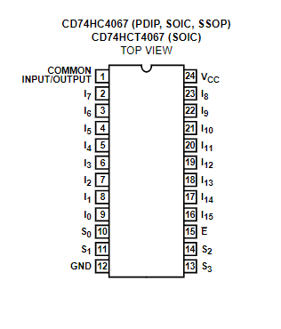
HC4067
74HC595
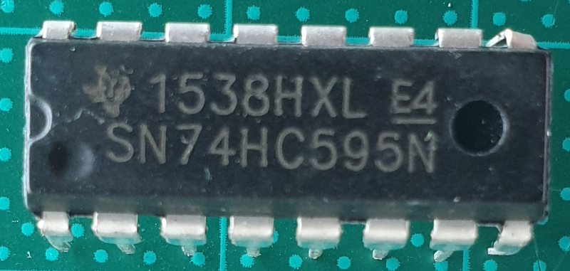
8-bit serial-in, serial or parallel-out shift register with output latches; 3-state
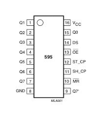
The 74HC595; 74HCT595 is an 8-bit serial-in/serial or parallel-out shift register with a storage register and 3-state outputs. Both the shift and storage register have separate clocks. The device features a serial input (DS) and a serial output (Q7S) to enable cascading and an asynchronous reset MR input. A LOW on MR will reset the shift register. Data is shifted on the LOW-to-HIGH transitions of the SHCP input. The data in the shift register is transferred to the storage register on a LOW-to-HIGH transition of the STCP input. If both clocks are connected together, the shift register will always be one clock pulse ahead of the storage register. Data in the storage register appears at the output whenever the output enable input (OE) is LOW. A HIGH on OE causes the outputs to assume a high-impedance OFF-state. Operation of the OE input does not affect the state of the registers. Inputs include clamp diodes. This enables the use of current limiting resistors to interface inputs to voltages in excess of VCC.
Features
- Wide supply voltage range from 2.0 to 6.0 V
- CMOS low power dissipation
- High noise immunity
- 8-bit serial input
- 8-bit serial or parallel output
- Storage register with 3-state outputs
- Shift register with direct clear
- 100 MHz (typical) shift out frequency
- Latch-up performance exceeds 100 mA per JESD 78 Class II Level B
- Complies with JEDEC standards:
- JESD8C (2.7 V to 3.6 V)
- JESD7A (2.0 V to 6.0 V)
- Input levels:
- For 74HC595: CMOS level
- For 74HCT595: TTL level
- ESD protection:
- HBM JESD22-A114F exceeds 2000 V
- MM JESD22-A115-A exceeds 200 V
- Multiple package options
- Specified from -40 °C to +85 °C and from -40 °C to +125 °C
Pin
#31, IC.01.4.A
Datasheet
4051
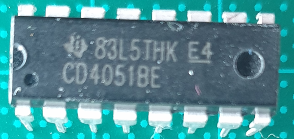
Adding Additional Analog Inputs in Arduino
Multiplexers are integrated circuits similar to an automated selector switch, allowing a system to read inputs from several sensors in quick succession.
HC4067 16-kanaals Analoge Multiplexer
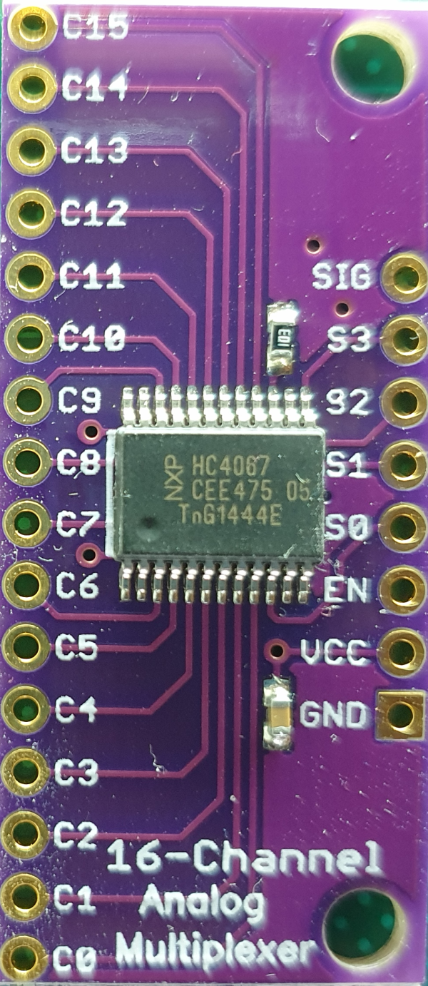
The MC74HC4067A utilizes silicon gate CMOS technology to achieve fast propagation delays, low ON resistances, and low OFF channel leakage current . This bilateral switch/multiplexer/demultiplexer controls analog and digital voltages that may vary across the full power supply range (from VCC to GND). The ON/OFF control inputs are compatible with standard CMOS outputs; with pullup resistors, they are compatible with LSTTL outputs.
Pin
Features
- Fast Switching and Propagation Speeds
- High ON/OFF Output Voltage Ratio
- Low Crosstalk Between Switches
- Diode Protection on All Inputs/Outputs
- Wide PowerSupply Voltage Range (VCC-GND) = 2.0 to 6.0 V
- Analog Input Voltage Range (VCC-GND) = 0 to 6.0 V
- Improved Linearity and Lower ON Resistance over Input Voltage
- Low Noise
- These are PbFree Devices
- Chip Enable Signals:Yes
- Configuration:Single 4:1
- Input Signal Type:Single
- Lead Finish:Matte Tin<
- Max Processing Temp:260
- Maximum Frequency (25 deg C) @ Vcc:90@4.5V MHz
- Maximum High Level Output Current:25 mA
- Maximum Low Level Output Current:25 mA
- Maximum On Resistance:160@4.5V Ohm
- Maximum On Resistance Range:150 to 250 Ohm
- Maximum Propagation Delay Bus to Bus:13@6V|15@4.5V|75@2V ns
- Maximum Turn-On Time:300@2V ns
- MSL Level:MSL 3 - 168 hours
- Number of Channels per Chip:1
- Number of Inputs per Chip:4
- Number of Outputs per Chip:1
- Operating Supply Current:4@6V mA
- Operating Supply Voltage:6, 2 V
- Operating Temperature:-55 to 125 °C
- Output Signal Type:Single-Ended
- Pin Count:24
- Type:Analog Multiplexer
#3, IC.01.4.B
Datasheet