NodeMCU
De nodeMCU is een van de populairste ontwikkelborden voor de ESP-12E module en de daarin opgenomen ESP8266EX system-on-chip. Deze kan net als een Arduino geprogrammeerd worden, maar dan met een 80 tot 160Mhz snelle processor en volledige wifi functionaliteit ingebouwd.
Er zijn naast Arduino ook nog andere software opties om met de nodeMCU te werken:
- De AT command firmware staat er al op, en laat je de wifi functies met seriële opdrachten interactief aansturen
- Er zijn script interpreter firmwares voor onder andere microPython en Lua
- En voor het zwaardere programmeerwerk is er de native C SDK omgeving (NONOS of RTOS) van Espressif, of esp-open-sdk als alternatief.
De nodeMCU/ESP8266 chip werkt op 3.3V logisch niveau voor datasignalen. De datasheet geeft 3.6V als maximum aan voor de input pinnen, dus er is voltage level conversie nodig als er met 5V sensors of processors gecommuniceerd wordt.
AT command interpreter:
Eenmaal met USB verbonden, kan de nodeMCU direct getest worden vanuit de serial monitor van de Arduino IDE.
Als de nodeMCU (her)start, geeft de ESP8266 bootloader eerst enige output op 74880 baud (op 115200 zie je dit als onleesbare tekens terug). Vervolgens start de AT firmware, en die geeft op 115200 baud ‘ready’ aan.
Met de serial monitor op 115200 baud, en de regeleinde optie op NL+CR, kun je opdrachten geven en de reactie zien, zoals:
- AT+GMR – vraagt de versie informatie op
- AT+CWMODE=1 – zet de module in station mode (client)
- AT+CWLAP – geeft een lijst van beschikbare access points
- AT+CWJAP=”ssid”,”password” – geeft opdracht te verbinden met access point
- AT+CWJAP? – vraagt informatie over het verbonden access point op
Alle at-instructies
4a-esp8266_at_instruction_set_en_v2.2.1.pdf
Als je een Arduino sketch uploadt, overschrijf je de AT command firmware. Wil je die daarna herstellen, dan kun je daarvoor de Espressif flash download tool gebruiken.
Layout
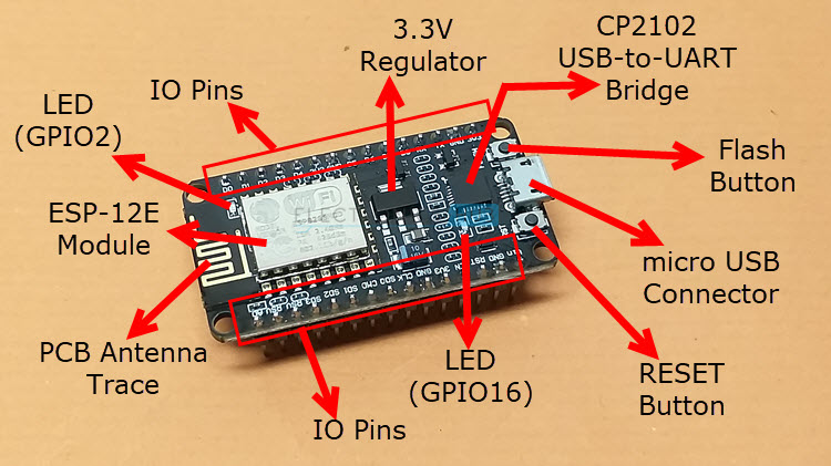
the NodeMCU board consists of 30 Pins (15 on each side), an ESP-12E Module with PCB Antenna, CP2102 USB to UART Bridge Controller from Silicon Labs, two push buttons (one is RESET and the other is Flash), a micro–USB Connector for Power and Uploading, a 3.3V Regulator, some passive and active components and two LEDS.
Pinout
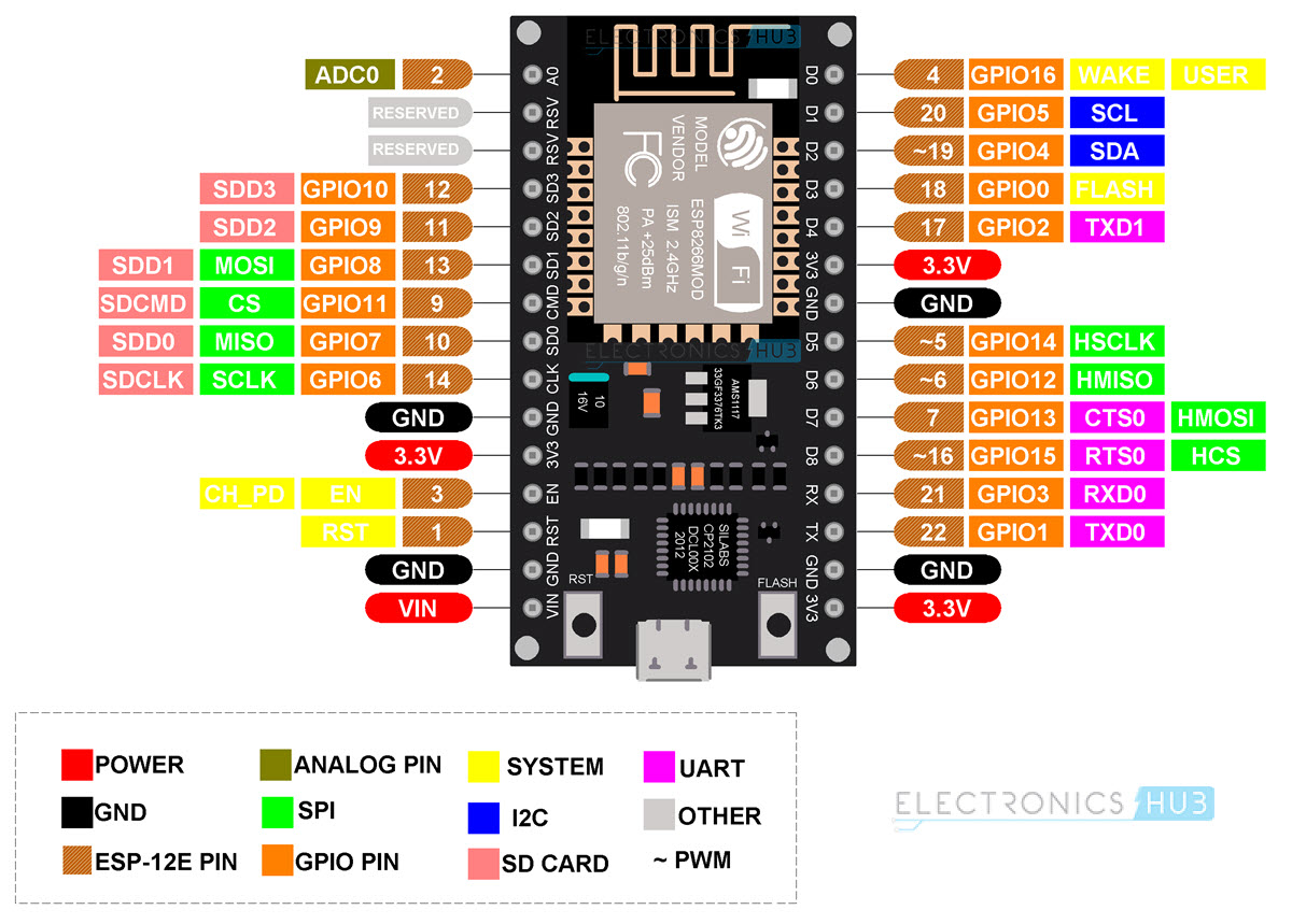
| Pin | Description | Alternate Functions | Default |
| ADC0 | Analog Input | | ADC0 |
| Reserved |
| Reserved |
| SDD3 | SDIO Data 3 | GPIO10 | SDD3 |
| SDD2 | SDIO Data 2 | GPIO9 | SDD2 |
| SDD1 | SDIO Data 1 | GPIO8 | SDD1 |
| SDDCMD | SDIO CMD | GPIO11 | SDDCMD |
| SDD0 | SDIO Data 0 | GPIO7 | SDD0 |
| SDCLK | SDIO CLK | GPIO6 | SDCLK |
| GND | Ground |
| 3.3V | 3.3V Output |
| EN | Chip Enable (Active HIGH) |
| RST | Reset (Active LOW) |
| GND | Ground |
| VIN | 5V Input to 3.3V Regulator |
| 3.3V | 3.3V Output |
| GND | Ground |
| TXD0 | UART0 TXD | GPIO1 | TXD0 |
| RXD0 | USRT0 RXD | GPIO3 | RXD0 |
| GPIO15 | GPIO15 | HSPI_CS/RTS0 | GPIO15 |
| GPIO13 | GPIO13 | HSPI_MOSI/CTS0 | GPIO13 |
| GPIO12 | GPIO12 | HSPI_MISO | GPIO12 |
| GPIO14 | GPIO14 | HSPI_SCK | GPIO14 |
| GND | Ground |
| 3.3V | 3.3V Output |
| GPIO2 | GPIO2 | UART1 TXD | GPIO2 |
| Flash | Flash | GPIO0 | Flash |
| GPIO4 | GPIO4 | Software SDA (I2C) | GPIO4 |
| GPIO5 | GPIO5 | Software SCL (I2C) | GPIO5 |
| GPIO16 | GPIO16 | Wake (deep sleep) | GPIO16 |
Power
There are two ways to power the NodeMCU board. One is through the micro-USB port and the other is through VIN pin. Note that ESP8266EX SoC is compatible with only 3.3V. So, the NodeMCU board has 3.3V Regulator IC (AMS1117 – 3.3).
If you have regulated 5V power, then you can apply this to the VIN pin. There are three 3.3V pins, which are connected to the 3.3V output of the regulator.
Peripherals
GPIO
The ESP8266EX has 17 GPIO pins. But not all them available for the user as some of these are used for their alternative functions (like UART, SDIO, SPI etc.) in NodeMCU (ESP-12E Module).
SPI
There are two SPI Interfaces on ESP8266EX SoC (SPI and HSPI). Both support Master and Slave Operations. Master mode clock can be configured to 80 MHz while slave mode clock is up to 20 MHz.
- SCLK – GPIO6 (Not Available)
- MISO – GPIO7 (Not Available)
- MOSI – GPIO8 (Not Available)
- CS – GPIO11 (Not Available)
- HSPI_CLK – GPIO14
- HSPI_MISO – GPIO12
- HSPI_MOSI – GPIO13
- HSPI_CS – GPIO15
GPIO pins for SPI are multiplexed with some SDIO pins. Also, there is a 4MB SPI Flash on the ESP-12E Module connected through SPI Pins. So, you do not have access to SPI pins. You can only used HSPI pins for SPI communication.
I2C
Hardware I2C is not available in ESP8266 but is can implemented through software. GPIO4 and GPIO5 can be used as SDA and SCL as they do not have any other alternative functions.
UART
ESP8266EX has two hardware UARTs (UART0 and UART1) with baud rates up to 115200. In this, UART0 can be used for communication and it has data flow control as well. UART1 has only TX pin (its RX pin is used by SDD1) so, it can used for data logging.
- UART0 TX – GPIO3
- UART0 RX – GPIO1
- UART0 RTS – GPIO15
- UART0 CTS – GPIO13
- UART1 TX – GPIO2
- UART1 RX – GPIO8 (Not Available)
Additional Features
All the GPIO pins except GPIO16 support Interrupts.
There are two on-board LEDs on the NodeMCU Board. One LED is on the ESP-12E Module and is connected to GPIO2 and the other LED is on the NodeMCU Board and this is connected to GPIO16.
GPIO Pins
GPIO6 – GPIO11 are used for SPI Flash. So, these are not available for user.
Also, GPIO1 and GPIO3 are used as UART TX and RX Pins, which also rules them out. So, out of 17 GPIO pins, 8 are already used for other purposes. This leaves us with 9 pins. These pins are marked as D0 to D8 on NodeMCU Board.
| GPIO Pin | NodeMCU Pin | Information |
| 0 | D3 | Pulled HIGH and connected to Flash Button |
| 1 | TX | Do not use while TXing |
| 2 | D4 |
| 3 | RX | Do not use while RXing |
| 4 | D2 | I2C SDA |
| 5 | D1 | I2C SCL |
| 6-11 | - | Connected to SPI Flash |
| 12 | D6 |
| 13 | D7 |
| 14 | D5 |
| 15 | D8 | Pulled LOW |
| 16 | D0 | Used to wake from deep sleep. No interrupt, I2C, PWM |
Boot Mode Selection Pins
| GPIO 0 | GPIO 2 | GPIO 15 | Boot Mode |
| LOW | HIGH | LOW | UART Bootloader |
| HIGH | HIGH | LOW | Boot from SPI Flash |
| x | x | HIGH | Boot from SDIO |
#6, Bak 5.10.A
github