ESP32-CAM WiFi+Bluetooth Development Board with ESP32S and OV2640 Camera Module
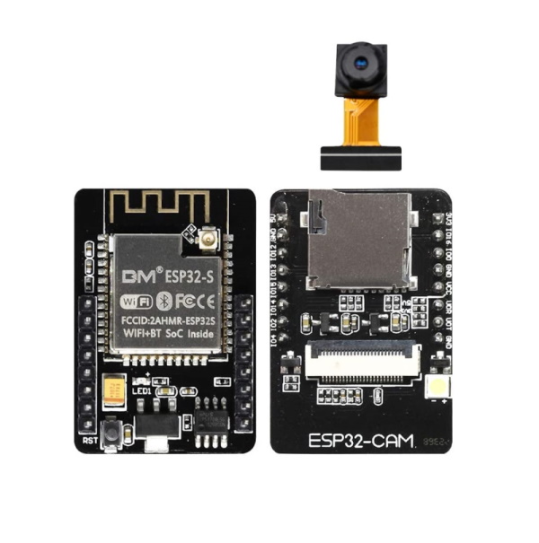
The ESP32CAM is a tiny module based on ESP32S module which comes with OV2640 Camera module. You can even program the ESP32CAM through the ESP-IDF by installing the ESP32 Core. The ESP32CAM equips the ESP32 with everything necessary to program, run and develop on the wonderchip. Additionally, the board reserved the MPU6050,BME280 and an analog MIC. ESP integrates WiFi, traditional bluetooth and BLE Beacon, with 2 high-performance 32-bit LX6 CPUs, 7-stage pipeline architecture, main frequency adjustment range 80MHz to 240MHz, on-chip sensor, Hall sensor, temperature sensor, etc. Fully compliant with WiFi 802.11b/g/n/e/i and bluetooth 4.2 standards, it can be used as a master mode to build an independent network controller, or as a slave to other host MCUs to add networking capabilities to existing devices. ESP32-CAM can be widely used in various IoT applications. It is suitable for home smart devices, industrial wireless control, wireless monitoring, QR wireless identification, wireless positioning system signals and other IoT applications. It is an ideal solution for IoT applications.
Features
- Ultra-small 802.11b/g/n Wi-Fi BT/BLE SoC module
- Low-power dual-core 32-bit CPU for application processors
- Up to 240MHz, up to 600 DMIPS
- Built-in 520 KB SRAM, external 4M PSRAM
- Supports interfaces such as UART/SPI/I2C/PWM/ADC/DAC
- Support OV2640 and OV7670 cameras with built-in flash
- Support for images WiFI upload
- Support TF card
- Support multiple sleep modes
- Embedded Lwip and FreeRTOS
- Support STA/AP/STA AP working mode
- Support Smart Config/AirKiss One-click distribution network
- Support for serial local upgrade and remote firmware upgrade (FOTA)
- Support secondary development
Technical Specification
| Module model | ESP32-CAM |
| Package | DIP-16 |
| Size | 27*40.5*4.5(±0.2)mm |
| SPI Flash | default 32Mbit |
| RAM | internal520KB+external 4M PSRAM |
| Bluetooth | bluetooth4.2BR/EDR and BLE standards |
| Wi-Fi | 802.11 b/g/n/e/i |
| Support interface | UART, SPI, I2C, PWM |
| Support TF card | Maximum support 4G |
| IO port | 9 |
| Serial port rate | default 115200 bps |
| Image output format | JPEG (only supported by OV2640), BMP, GRAYSCALE |
| Spectrum range | 2412 ~ 2484MHz |
| Antenna form | onboard PCB antenna, gain 2dBi |
| Transmit power |
- 802.11b: 17±2 dBm (@11Mbps)
- 802.11g: 14±2 dBm (@54Mbps)
- 802.11n: 13±2 dBm (@MCS7)
|
| Receiving sensitivity |
- CCK, 1 Mbps : -90dBm
- CCK, 11 Mbps: -85dBm
- 6 Mbps (1/2 BPSK): -88dBm
- 54 Mbps (3/4 64-QAM): -70dBm
- MCS7 (65 Mbps, 72.2 Mbps): -67dBm
|
| Power consumption |
- Turn off the flash: 180mA@5V
- Turn on the flash and adjust the brightness to the maximum: 310mA@5V
- Deep-sleep: The lowest power consumption can reach 6mA@5V
- Modern-sleep: up to 20mA@5V
- Light-sleep: up to 6.7mA@5V
|
| Security | WPA/WPA2/WPA2-Enterprise/WPS |
| Power supply range | 5V |
| Operating temperature | -20 °C ~ 85 °C |
| Storage environment | -40 °C ~ 90 °C, < 90%RH |
Notes
- Please ensure that the module input power is at least 5V 2A, otherwise the image will unstable.
- ESP32 GPIO32 pin controls camera power. When the camera is working, please pull GPIO32 low.
- Since IO0 is connected to the camera XCLK, please leave IO0 floating when using it. Do not connect high and low level.
- The factory has the default firmware, no additional download is available. Please handle it carefully if you need to re-burn other firmware.
Pins
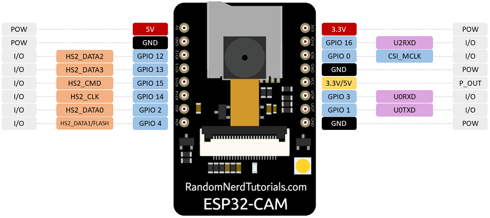
The ESP32-CAM comes with three GND pins (colored in black color) and two power pins (colored with red color): 3.3V and 5V.
You can power the ESP32-CAM through the 3.3V or 5V pins. However, many people reported errors when powering the ESP32-CAM with 3.3V, so we always advise to power the ESP32-CAM through the 5V pin.
There’s also the pin labeled on the silkscreen as VCC (colored with a yellow rectangle). You should not use that pin to power the ESP32-CAM. That is an output power pin. It can either output 5V or 3.3V.
In our case, the ESP32-CAM outputs 3.3V whether it is powered with 5V or 3.3V. Next to the VCC pin, there are two pads. One labeled as 3.3V and other as 5V.
If you look closely, you should have a jumper on the 3.3V pads. If you want to have an output of 5V on the VCC pin, you need to unsolder that connection and solder the 5V pads.
GPIO 1 and GPIO 3 are the serial pins (TX and RX, respectively). Because the ESP32-CAM doesn’t have a built-in programmer, you need to use these pins to communicate with the board and upload code.br>
GPIO 0 determines whether the ESP32 is in flashing mode or not. When GPIO 0 is connected to GND, the ESP32 is in flashing mode.
GPIO 16 is by default a UART pin. However, you can use it as input. It is internally connected to a 10k Ohm pull-up resistor.
There are three GND pins (black color) and two power pins (red color): 3.3V and 5V. The board can be powered through the 3.3V or 5V pins. However, a lot of people recommend powering the board through the 5V pin. So, we will respect that.
These pins are internally connected to the microSD card reader:
- GPIO 14: CLK
- GPIO 15: CMD
- GPIO 2: Data 0
- GPIO 4: Data 1 (also connected to the on-board LED)
- GPIO 12: Data 2
- GPIO 13: Data 3
If the pins are not being used for microSD card, you can use these pins as regular inputs/outputs. All these GPIOs are RTC and support ADC: GPIOs 2, 4, 12, 13, 14, and 15.
GPIO 33 is an onboard LED, that is next to the RST button. That onboard LED works with inverted logic, so you send a LOW signal to turn it on and a HIGH signal to turn it off.
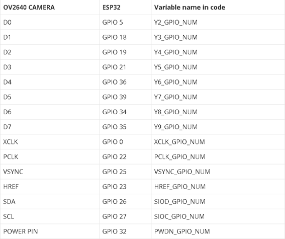
The camera connections between the camera and the ESP32-CAM AI-Thinker are shown in the image below.
Blink circuit
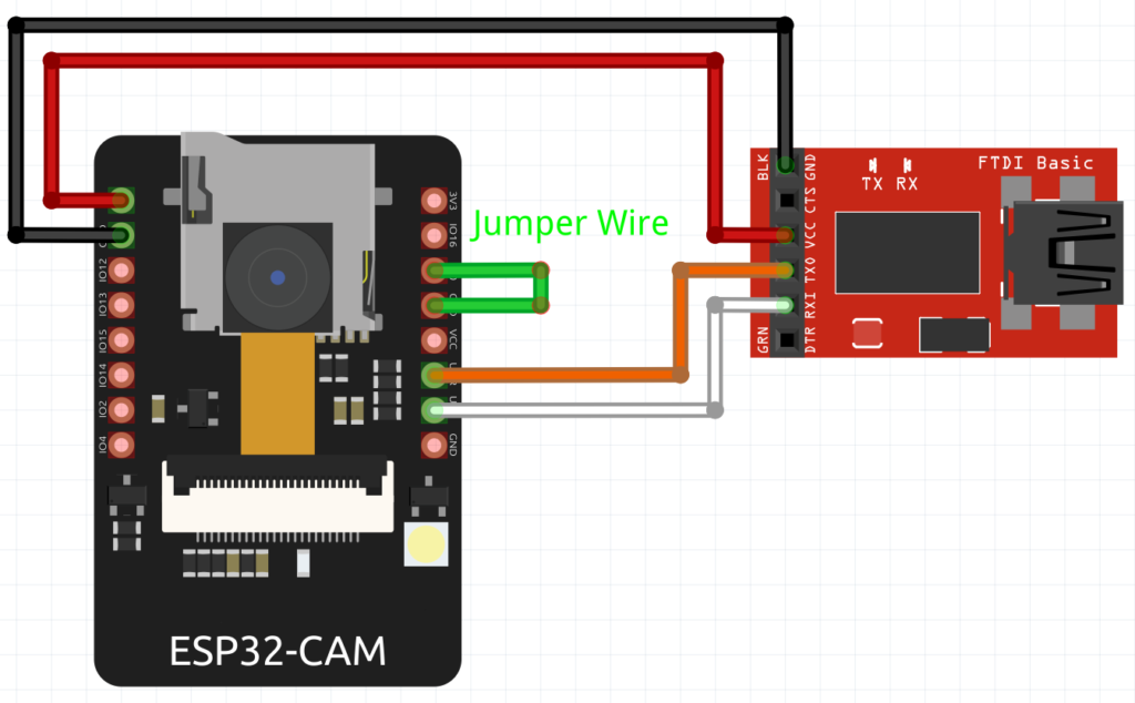
The board can be powered by any power supply available, like a battery or USB port on your computer. In this setup, it will be powered through a USB port via the FTDI power pins, like in figure 4. So start by connecting the FTDI GND to the Board GND and do the same with VCC. Connect the (Orange wire) FTDI TX to the Board RX and FTDI RX to the Board TX (White wire).
Since, GPIO 0, determines whether the ESP32 is in flashing mode or not, we need to connect GPIO 0 to GND to turn the ESP32 is in flashing mode. After uploading the code, the GPIO 0 must be disconnected from the GND pin.
The development board can be programmed using Arduino IDE, but for that, we need to use an FTDI. After completing the schematic above, we can connect the FTDI to the computer.
To upload code to the board, follow the next steps:
-
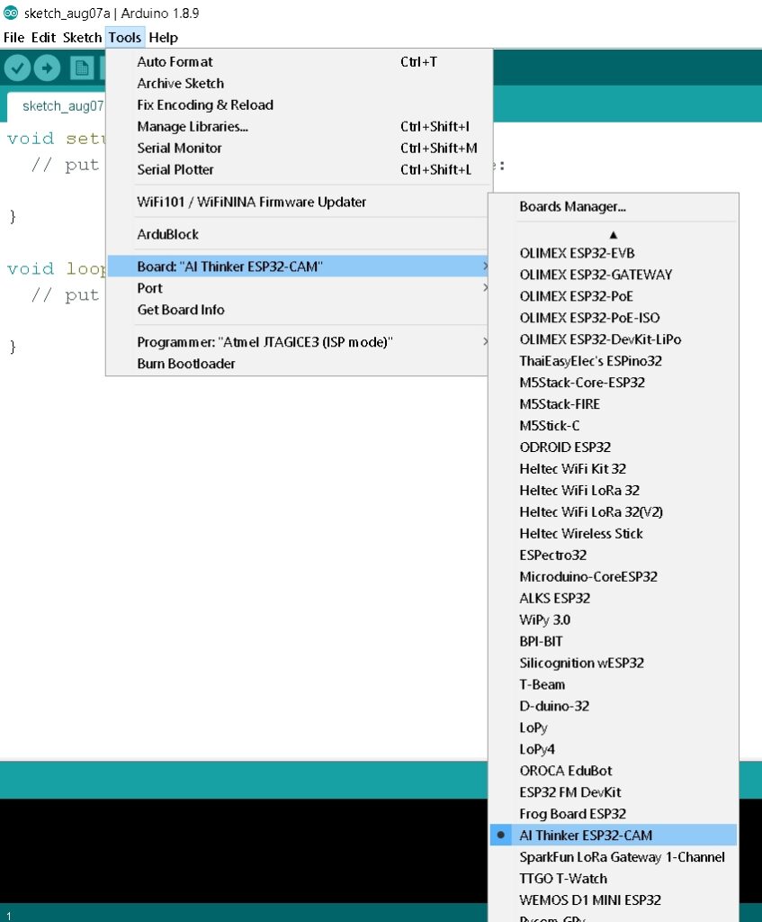
Go to Tools > Board and select AI-Thinker ESP32-CAM. You must have the ESP32 add-on installed. Otherwise, this board won’t show up on the Boards menu. If you have not done the installation, there is a guide below on how to do it.
-
Go to Tools > Port and select the COM port the board is connected to.
-
For simplicity, you can upload a blank sketch to your board.
-
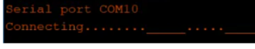
When you start to see some dots on the debugging window, press the on-board RST button. After a few seconds, the code should be successfully uploaded to the board.
-
When you see the “Done uploading” message, remember to remove GPIO 0 from GND and press the on-board Reset button to get the board ready.
Install the ESP32 Library and Add-on
Follow the next steps to install the ESP32 add-on and board on arduino IDE.
-
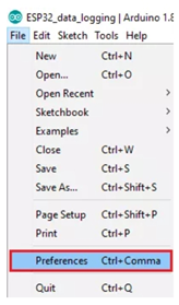
In your Arduino IDE, go to File> Preferences
-
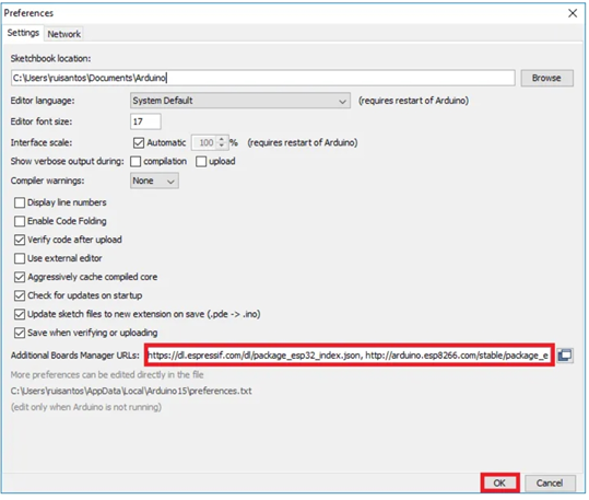
Enter https://dl.espressif.com/dl/package_esp32_index.json into the “Additional Board Manager URLs” red field in the figure below. Then, click the “OK” button:
-
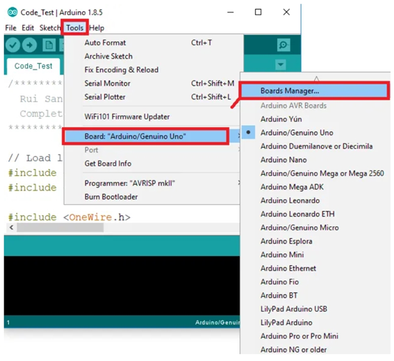
Open the Boards Manager. Go to Tools > Board > Boards Manager
-
Search for ESP32 and press install button for the “ESP32 by Espressif Systems“. It should be instaled after a few seconds.
After you make these steps, the ESP32-CAM board should be ready. Plug the ESP32 board into your computer. In your Arduino IDE open Tools > Board menu and select the board, like figure 10. In our case is AI-Thinker ESP32-CAM. Select the correct port and it is ready to program.
            //LED BUILT_IN is GPIO 33
            void setup() {
              pinMode(33, OUTPUT); // Set the pin as output
            }

            // Remember that the pin work with inverted logic
            // LOW to Turn on and HIGH to turn off
            void loop() {
              digitalWrite(33, LOW); //Turn on
              delay (1000); //Wait 1 sec
              digitalWrite(33, HIGH); //Turn off
              delay (1000); //Wait 1 sec
            }
ESP32 technical reference manual
#1, Bak 5.05.A