Arduino motorshield
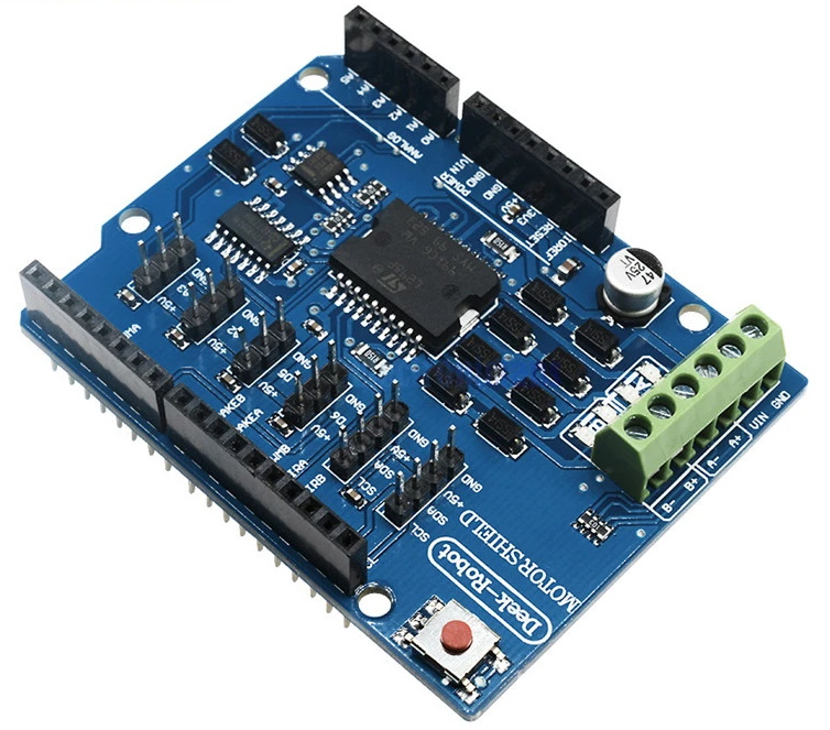
The Arduino Motor Shield is a shield that lets you control various loads that a typical Arduino pin cannot drive. The motor shield has quite a few features such as current measuring and the ability to drive a single stepper motor. At the heart of this shield is the L298P dual full bridge driver that can handle up to 3 amps for very short durations or 2 amps continuously per channel.
Power Supply Requirements
The motors attached to the motor shield need an ample power supply. By using the USB connection, the current will often be limited to 500mA or 1 amp. Many motors will draw more current than the amount the USB source can supply. To reduce the risk of possible damange to a usb port an external power supply should be used.
In order to used this shield, you need to initialize several of the pins used by the shield. This setup code is typically placed in the setup function. To use all the functionality of the shield, pins 8,9,12, and 13 need to be initialized as output pins.
pinMode(8,OUTPUT); //Channel A Brake Pin Initialize
pinMode(9,OUTPUT); //Channel B Brake Pin Initialize
pinMode(12,OUTPUT); //Channel A Direction Pin Initialize
pinMode(13,OUTPUT); //Channel B Direction Pin Initialize
Direction Control
To control the motor’s direction, Pin 12 (Channel A) and Pin 13 (Channel B) are used. To drive the motor forward* this pins needs to be brought high. The pins can be driven low to put the motors into reverse.
Important note: Changing direction rapidly can cause unexpected effects. From a mechanical standpoint, going from forward to reverse rapidly could potentially damage a gear box. From an electrical standpoint, it can cause large current and voltage spikes. To resolve these issues, a motor needs to be taken from one direction to another with a small pause inbetween. An example of this can be found in Basic_Control.ino, attached.
*Since the “forward” direction of the motors depends on application, for this tutorial "forward" will refer to positive voltage on the + screw terminal on the shield.
Speed Control
To control the motors speed Pin 3 (Channel A) and Pin 11 (Channel B) can use PWM signals to vary the speed of the motors. To use the PWM feature on the arduino the analogWrite function needs to be called. In the function a pin needs to be defined and a speed between 0-255 needs to defined. An example of this can be found in Basic_Control.ino, attached.
Braking
The motor driver on the Arduino Motor Shield has the ability to apply an engine brake. The brake works by shorting both terminals of the motor together. The brake is controlled by Pin 8 (Channel A) and Pin 9 (Channel B).
Current Sensing
Another feature of the Arduino Motor Shield is the ability to determine the amount of current the motor (or any inductive load) is drawing. Current sensing can be useful for robotics applications, such as traction control and determining if the robot is pushing an object. The current sense pins are A0 (Channel A) and A1 (Channel B). The Motor Shield will output 3.3v on the current sense pins when the maximum channel current (2 amps) is reached.
After a small amount of math, it can be determined that each integer will represent 2.96mA. So for example, if the analogRead(A0) produces a value of 121 the motor (or load) is drawing 0.36 amps. An example of this can be found in Current_to_Serial.ino, attached.
| Werking Voltage | 5V to 12V |
| Motor controller | L298P, Stuurt 2 DC motors of 1 stepper motor aan |
| Max Stroom | 2A per channel or 4A max (met een externe voeding) |
| Stroom gevoeligheid | 1.65V/A |
| | Free running stop and brake function |
| Functie | pins per Ch. A | pins per Ch. B |
| Richting | D12 | D13 |
| PWM | D3 | D11 |
| Brake | D9 | D8 |
| Stroom gevoeligheid | A0 | A |
#3, Bak 5.08