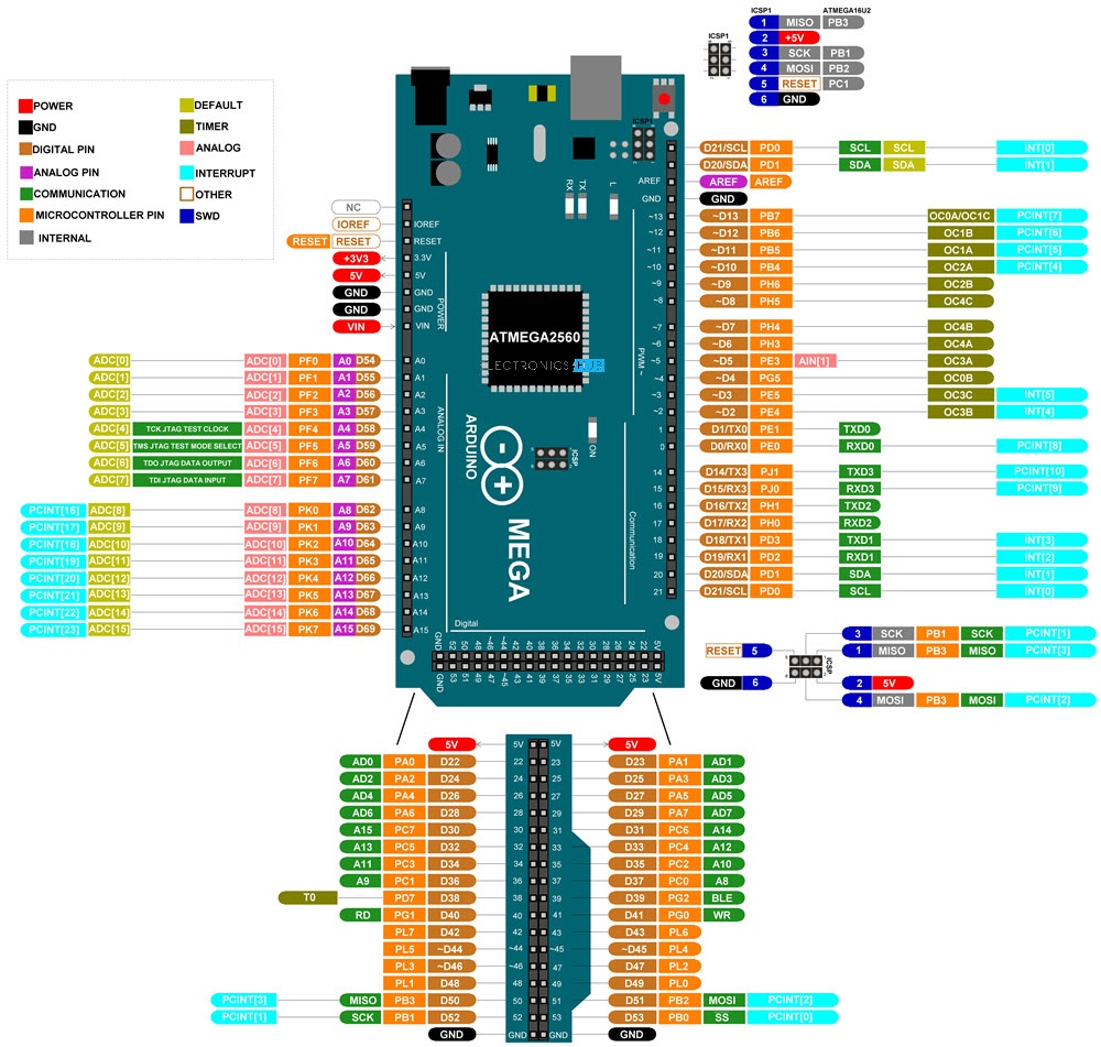
Arduino MEGA
Arduino Mega is based on ATmega2560 Microcontroller, an 8-bit AVR Architecture based MCU from ATMEL. It is available in a 100-pin Quad Flat Package.
It is designed and developed to provide more number of IO lines (both Digital and Analog), more flash memory and more RAM when compared to UNO.
Arduino Mega Board Layout
Technical Specifications
| MCU | ATmega2560 |
| Architecture | AVR |
| Operating Voltage | 5V |
| Input Voltage | 6V – 20V (limit) 7V – 12V (recommended) |
| Clock Speed | 16 MHz |
| Flash Memory | 256 KB (8 KB of this used by bootloader) |
| SRAM | 8 KB |
| EEPROM | 4 KB |
| Digital IO Pins | 54 (of which 15 can produce PWM) |
| Analog Input Pins | 16 |
Power up
- Type-B USB Connector
- Provide an unregulated supply in the range of 6V to 20V to VIN pin
- Unregulated supply through the 2.1mm DC Jack
Input and Output Pins
Of the 86 pins available on the Mega board, 72 pins are associated with input and output. In that 54 pins (D0 to D53) are true digital IO pins, which can be configured as per you application using pinMode(), digitalWrite() and digitalRead() functions.
All these Digital IO pins are capable of sourcing or sinking 20mA of current (maximum 40mA is allowed). An additional feature of the Digital IO pins is the availability of internal pull-up resistor (which is not connected by default). The value of the internal pull-up resistor will be in the range of 20KΩ to 50KΩ.
There are also 16 Analog Input Pins (A0 to A15). All the analog input pins provide a 10-bit resolution ADC feature, which can be read using analogRead() function.
An important point about Analog Input pins is that they can be configured as Digital IO pins, if required.
Digital IO pins 2 – 13 and 44 – 46 are capable of producing 8-bit PWM Signals. You can use analogWrite() function for this.
Communication Interfaces
Perhaps the most common communication interface in the Arduino universe is the Serial Communication. In fact, the Arduino boards (UNO or Nano or Mega) are programmed using the serial communication.
Arduino Mega supports four hardware Serial Communication interfaces. Digital IO pins 0 and 1 are used as Serial RX0 and TX0 pins to receive and transmit serial data. These pins are connected to the serial pins of the on-board USB to Serial Converter IC.
Similarly. Digital IO pins 19 and 18 as RX1 and TX1, 17 and 16 as RX2 and TX2 and 15 and 14 as RX3 and TX3 respectively.
Digital IO Pins 20 and 21 can be configured as SDA (20) and SCL (21) to support I2C or I2C or Two Wire Interface (TWI) communication.
The final communication interface is the SPI. Digital IO Pins 50, 51 52 and 53 can be configured as SPI pins MISO, MOSI, SCK and SS respectively.
Miscellaneous
There is an on-board LED connected to digital IO pin 13. Use this LED to perform Blinky operations. The reference voltage for the internal ADC is by default set to 5V. But using the AREF pin, you can manually set the upper limit of the ADC.
Using the IOREF pin, you can set the reference voltage for Microcontroller operations.
To reset the microcontroller, you can use the on-board RESET button.
Although you can program the Arduino Mega using the USB cable, there is a provision to program the MCU using the In-Circuit Serial Programming (ICSP) interface.
The UART bootloader, which is preloaded in to the ATmega2560 Microcontroller, enables programming through serial interface. But ICSP doesn’t need any bootloader. You can program Arduino Mega using ISCP or use the ISCP of Arduino Mega to program other Arduino Boards.
Digital IO Pins 2, 3, 18, 19, 20 and 21 can be configured as External Interrupts Pins INT0, INT1, INT5, INT4, INT3 and INT2 respectively. Use attachInterrupt() function to configure the Interrupt for rising edge, falling edge or level change on the pin.
If you want use any Shields, then Arduino Mega is perfectly compatible with most of shields designed for Arduino UNO.
Pinout
#4, Bak G5.04