IR Sensor Module Circuit
Sensors are very important part of electronics, especially in Robotics and Automations. Sensors in electronic devices make our life easy by automatically sense and control the devices, without human interaction. There are many kinds of sensors like Fire sensor, humidity sensor, motion sensor, temperature sensor, IR sensor etc. In this article, we will explain about IR sensor (Infrared sensor), how it works and how to build an IR sensor Module.
IR sensor is very popular sensor, which is used in many applications in electronics, like it is used in Remote control system, motion detector, Product counter, Line follower Robots, Alarms etc.
IR sensor basically consist an IR LED and a Photodiode, this pair is generally called IR pair or Photo coupler. IR sensor work on the principal in which IR LED emits IR radiation and Photodiode sense that IR radiation. Photodiode resistance changes according to the amount of IR radiation falling on it, hence the voltage drop across it also changes and by using the voltage comparator (like LM358) we can sense the voltage change and generate the output accordingly.
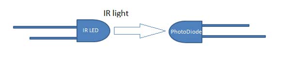
The placing of IR LED and Photodiode can be done in two ways: Direct and Indirect. In Direct incidence, IR LED and photodiode are kept in front of one another, so that IR radiation can directly falls on photodiode. If we place any object between them, then it stops the falling of IR light on photodiode.
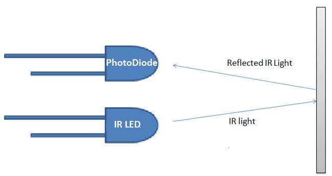
And in Indirect Incidence, both the IR LED and Photo diode are placed in parallel (side by side), facing both in same direction. In that fashion, when a object is kept in front of IR pair, the IR light gets reflected by the object and gets absorbed by photodiode. Note that object shouldn’t be black as it will absorb all the IR light, instead of reflect. Generally IR pair is placed in this fashion in IR sensor Module.
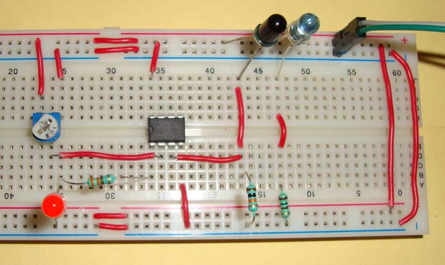
To build an IR module, we mainly need IR pair (IR LED and Photodiode) and LM358 with some resistors and a LED.
IR LED
IR LED emits light, in the range of Infrared frequency. IR light is invisible to us as its wavelength (700nm – 1mm) is much higher than the visible light range. Everything which produce heat, emits infrared like for example our human body. Infrared have the same properties as visible light, like it can be focused, reflected and polarised like visible light.
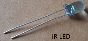
IR LED looks like a normal LED and also operates like a normal LED, it consumes 20mA current and 3vots power. IR LEDs have light emitting angle of approx. 20-60 degree and range of approx. few centimetres to several feets, it depends upon the type of IR transmitter and the manufacturer. Some transmitters have the range in kilometres.
PhotoDiode
Photodiode is considered as Light dependent Resistor (LDR), means it has very High resistance in absence of light and become low when light falls on it. Photodiode is a semiconductor which has a P-N junction, operated in Reverse Bias, means it start conducting the current in reverse direction when Light falls on it, and the amount of current flow is proportional to the amount of Light. This property makes it useful for IR detection.
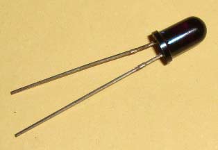
Photodiode looks like a LED, with a Black colour coating on its outer side. It is used in reversed biased, as showed in circuit diagram below.
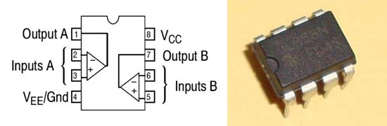
LM358
LM358 is an operational amplifier (Op-Amp) and in this circuit we are using it as a voltage comparator. The LM358 has two independent voltage comparators inside it, which can be powered by single PIN, so we can use the single IC to build two IR sensor modules. We have used only one comparator here, which have inputs at PIN 2 & 3 and output at PIN 1. Voltage comparator has two inputs, one is inverting input and second is non-inverting input (PIN 2 and 3 in LM358). When voltage at non-inverting input (+) is higher than the voltage at inverting input (-), then the output of comparator (PIN 1) is High. And if the voltage of inverting input (-) is Higher than non-inverting end (+), then output is LOW.
IR sensor Module
Components
-
IR pair (IR LED and Photodiode)
-
IC LM358
-
Resistor 100, 10k, 330 ohm
-
Variable resistor – 10k
-
LED
You can see the connections in the IR sensor circuit diagram. Photo diode is connected in reverse bias, inverting end of LM358 (PIN 2) is connected to the variable resistor, to adjust the sensitivity of the sensor. And non-inverting end (PIN 3) is connected to the junction of photodiode and a resistor.
When we turn ON the circuit there is no IR radiation towards photodiode and the Output of the comparator is LOW. When we take some object (not black) in front of IR pair, then IR emitted by IR LED is reflected by the object and absorbed by the photodiode. Now when reflected IR Falls on Photodiode, the voltage across photodiode drops, and the voltage across series resistor R2 increases. When the voltage at Resistor R2 (which is connected to the non-inverting end of comparator) gets higher than the voltage at inverting end, then the output becomes HIGH and LED turns ON.
Voltage at inverting end, which is also called Threshold Voltage, can be set by rotating the variable resistor’s knob. Higher the voltage at inverting end (-), less sensitive the sensor and Lower the voltage at inverting end (-), more sensitive the sensor.