17. Optocoupler 4N35
An optocoupler or optoisolator chip is a chip that allows for electrical isolation between the input of the circuit and the output of the circuit.
By electrical isolation, we mean that the power going into the input has no effect whatsoever on the power on the output. The power sources are isolated, so they are completely independent. So if the power to the input is changed, this does not affect the power on the output, and vice versa.
Electrical isolation can be very important, especially in circuits where the input power to the circuit is very high and there are other parts in the circuit that only require a very small amount of power. So if there is an incident such as a surge of power into the input of the circuit, it doesn't affect the area that only requires a small amount of power, since it's isolated from the input. This would be the main application and use for optoisolators. Optocouplers can also be used if the input power may bring in a lot of noise, which for many applications can be very undesirable. To separate this noise from being induced into the output, electrical isolation is necessary and solves the problem.
How optocouplers work is they provide isolation through an IR LED and phototransistor. With this setup, there's no direct conductive path from the input to the output of the circuit. Instead, an IR LED beams its infrared light onto the phototransistor. Being that there's no direct conductive pathway, the input and output aren't linked, so there's electrical isolation.
The 4N35 is a 6-pin IC. Its pinout is shown below.
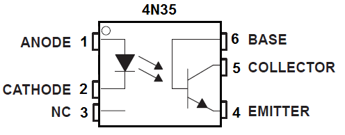
| 1 | Anode | The input voltage to turn on the IR LED is connected here. |
| 2 | Cathode | This connects to ground. |
| 3 | NC | This remains unconnected. |
| 4 | Emitter | The emitter gets connected to ground. |
| 5 | Collector | The output and power connects to the collector terminal. |
| 6 | Base | This remains unconnected. |
Give enough power to the anode and cathode pins, so that the LED is sufficient power to turn on. Once on, it beams infrared light onto the phototransistor. With infrared, the phototransistor can conduct across from collector to emitter and power on any load connected to the output, which in this case is a LED.
And now there is isolation between the input and output of the circuit.
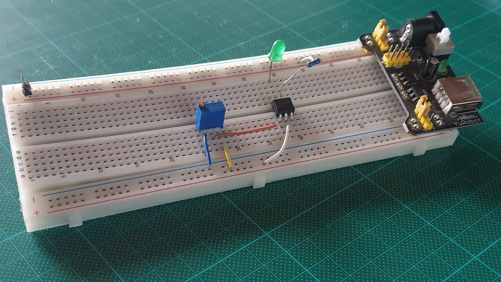
Connection
One side is powered by the M102.
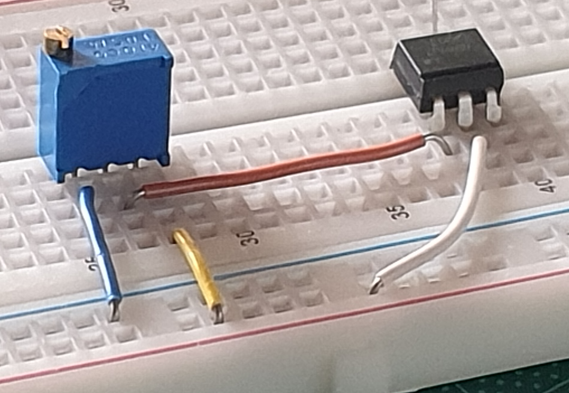
- 5v => trimpot
- Ground => trimpot
- Trimpot => Anode 4N35
- Ground 4N35 => Ground
The other side
- 5V => LED => Collector 4N35
- Ground => Emitter 4N35