|
|
11. Shift Register 74HC595N 8 led aansturing
At sometime or another you may run out of pins on your Arduino board and need to extend it with shift registers. You can use the 74HC595. The datasheet refers to the 74HC595 as an "8-bit serial-in, serial or parallel-out shift register with output latches; 3-state." In other words, you can use it to control 8 outputs at a time while only taking up a few pins on your microcontroller. You can link multiple registers together to extend your output even more. (Users may also wish to search for other driver chips with "595" or "596" in their part numbers, there are many. The STP16C596 for example will drive 16 LED's and eliminates the series resistors with built-in constant current sources.)
How this all works is through something called "synchronous serial communication," i.e. you can pulse one pin up and down thereby communicating a data byte to the register bit by bit. It's by pulsing second pin, the clock pin, that you delineate between bits. This is in contrast to using the "asynchronous serial communication" of the Serial.begin() function which relies on the sender and the receiver to be set independently to an agreed upon specified data rate. Once the whole byte is transmitted to the register the HIGH or LOW messages held in each bit get parceled out to each of the individual output pins. This is the "parallel output" part, having all the pins do what you want them to do all at once.
The "serial output" part of this component comes from its extra pin which can pass the serial information received from the microcontroller out again unchanged. This means you can transmit 16 bits in a row (2 bytes) and the first 8 will flow through the first register into the second register and be expressed there. You can learn to do that from the second example.
"3 states" refers to the fact that you can set the output pins as either high, low or "high impedance." Unlike the HIGH and LOW states, you can"t set pins to their high impedance state individually. You can only set the whole chip together. This is a pretty specialized thing to do -- Think of an LED array that might need to be controlled by completely different microcontrollers depending on a specific mode setting built into your project. Neither example takes advantage of this feature and you won"t usually need to worry about getting a chip that has it.
Project
|
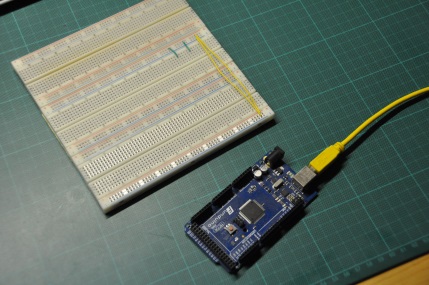
Starts with Breadboard and the arduino mega.
|
|
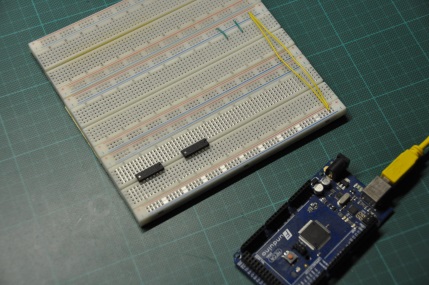
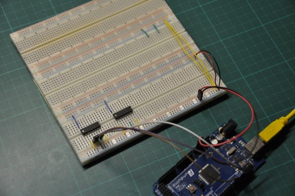
Place the 74HC595N.
|
|
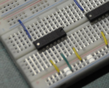
Wire IC Vcc and gnd with the breadboard.
| Pin 8 | gnd |
| Pin 10 | 5V |
| Pin 13 | gnd |
| Pin 16 | 5V |
|
|
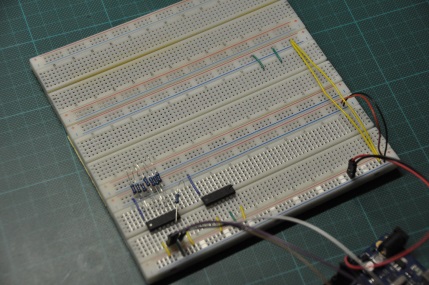
Wire Arduino GND and Vcc with the breadboard.
| Pin 14, Serial data input | Arduino pin 11 |
| Pin 11, Shift register clock pin | Arduino pin 12 |
| Pin 12, Storage register clock pin (latch pin) | Arduino pin 8 |
|
|
Place the resistors.
Q0 .. Q7
|
|
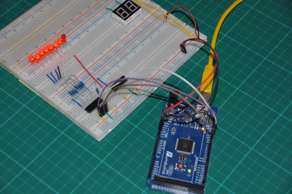
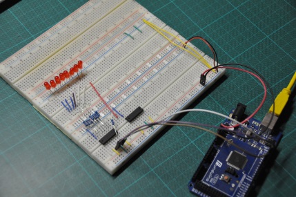
Place and wire the leds
|
Code
int latchPin = 8;
int clockPin = 12;
int dataPin = 11;

byte data;
byte dataArray[10];

void setup() {
  pinMode(latchPin, OUTPUT);

  dataArray[0] = 0xFF; //0b11111111
  dataArray[1] = 0xFE; //0b11111110
  dataArray[2] = 0xFC; //0b11111100
  dataArray[3] = 0xF8; //0b11111000
  dataArray[4] = 0xF0; //0b11110000
  dataArray[5] = 0xE0; //0b11100000
  dataArray[6] = 0xC0; //0b11000000
  dataArray[7] = 0x80; //0b10000000
  dataArray[8] = 0x00; //0b00000000
  dataArray[9] = 0xFF; //0b11100000

  blinkAll_2Bytes(2,500);
}

void loop() {
  for (int j = 0; j < 9; j++) {
    data = dataArray[j];
    digitalWrite(latchPin, 0);
    shiftOut(dataPin, clockPin, data);
    digitalWrite(latchPin, 1);
    delay(1000);
  }

  blinkAll_2Bytes(2,500);
}

void shiftOut(int myDataPin, int myClockPin, byte myDataOut) {
  int i=0;
  int pinState;
  pinMode(myClockPin, OUTPUT);
  pinMode(myDataPin, OUTPUT);

  digitalWrite(myDataPin, 0);
  digitalWrite(myClockPin, 0);
  for (i=7; i>=0; i--)  {
    digitalWrite(myClockPin, 0);

    if ( myDataOut & (1<<i) ) {
      pinState= 1;
    }
    else {
      pinState= 0;
    }

    digitalWrite(myDataPin, pinState);
    digitalWrite(myClockPin, 1);
    digitalWrite(myDataPin, 0);
  }

  digitalWrite(myClockPin, 0);
}

void blinkAll_2Bytes(int n, int d) {
  digitalWrite(latchPin, 0);
  shiftOut(dataPin, clockPin, 0);
  shiftOut(dataPin, clockPin, 0);
  digitalWrite(latchPin, 1);
  delay(200);
  for (int x = 0; x < n; x++) {
    digitalWrite(latchPin, 0);
    shiftOut(dataPin, clockPin, 255);
    shiftOut(dataPin, clockPin, 255);
    digitalWrite(latchPin, 1);
    delay(d);
    digitalWrite(latchPin, 0);
    shiftOut(dataPin, clockPin, 0);
    shiftOut(dataPin, clockPin, 0);
    digitalWrite(latchPin, 1);
    delay(d);
  }
}
74HC595 live
Download binary
Example Arduino Library ShiftRegister595
|