|
|
10. 7 Segment LED display
|
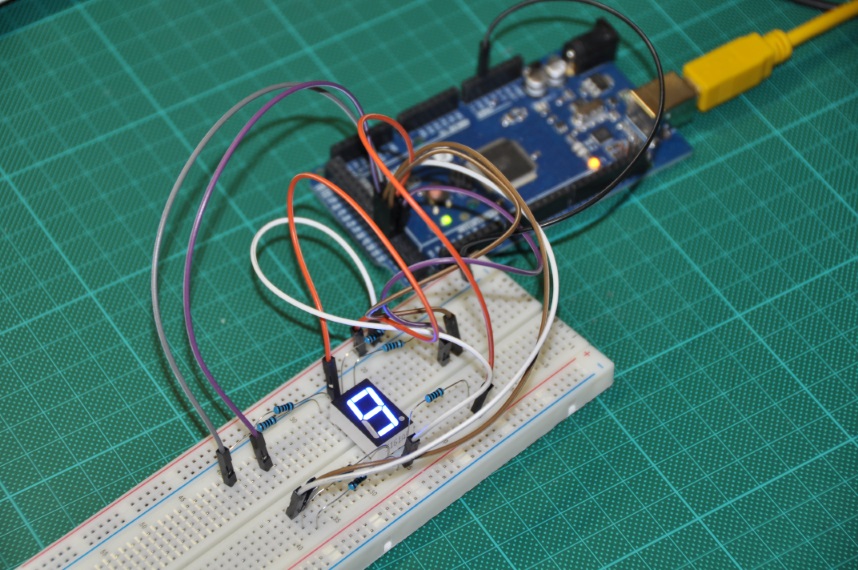
The circuit that we are going to build shown as a schematic; where A -G and DP connect to sequential output ports on the Arduino board. Each segment of the display has a resistor in series to lower the current through the LED's. Note that although it may seem quicker to connect one resistor to the common pin, this would alter the brightness of the LED's depending how many segments were turned on.
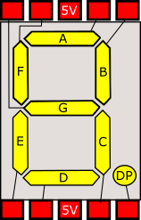
the graphical view of a 7 segment display showing one common arrangement for internal wiring and pin arrangement. This shows a common anode unit so the two center common pins are connected to 5V. For common cathode this would be GND.
|
|
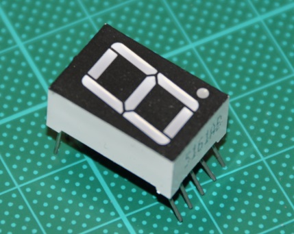
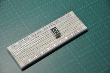
7 segment display
|
|
|
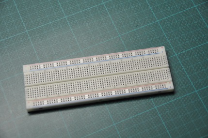
Breadboard
|
|
|
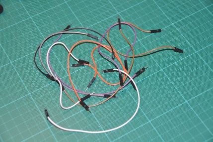
Wire
|
|
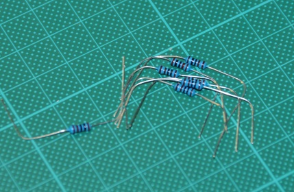
Resistors
7x
1k Ohm
|
|
|
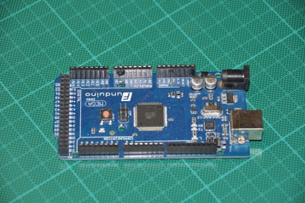
Arduino mega
|
|
Build
|
Place the 7 segment display
|
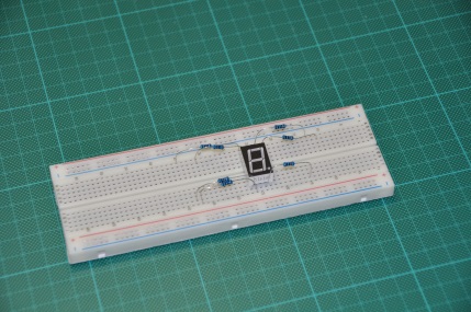
|
Resistors
|
|
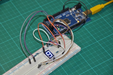
Connect the wires to the arduino
In the sources 'ledStart' is the first output port. The segment 'A' is connected to this port.
All other segments must follow on sequentially.
|
Code
The code has two variable:
-
ledStart is the first output port that you have used (for segment A and all other segments must follow on sequentially).
-
Common should be at either 5V or GND depending on polarity, variable commonHigh should be set to true if common is connected to 5V or false if common is connected to GND.
// set this to the first pin where wiring starts.
int ledStart = 30;

// set to true if the common pin is HIGH, false otherwise
boolean commonHigh = false;


void setup() {
  // Enable all A-G and DP and outputs,
  // set them to OFF (if common is high, then 1 is off).
  for (int i = 0; i < 8; ++i) {
    pinMode(ledStart + i, OUTPUT);
    digitalWrite(ledStart + i, commonHigh ? 1 : 0);
  }
}

void loop() {
  // write the number 0 - F (hex)
  // onto the display each half second

  //writeDigitToDisplay(1);

  for (int i = 0; i < 16; i++)
  {
    writeDigitToDisplay(i);
    delay(1000);
  }
}

// Now we define the bits that are on and off
// for each segment, These are used in the
// function below to turn the right bits on.
int dig[16] = {
  0b1111110,//0
  0b0110000,//1
  0b1101101,//2
  0b1111001,//3
  0b0110011,//4
  0b1011011,//5
  0b1011111,//6
  0b1110000,//7
  0b1111111,//8
  0b1111011,//9
  0b1110111,//a
  0b0011111,//b
  0b1001110,//c
  0b0111101,//d
  0b1001111,//e
  0b1000111 //f
};

void writeDigitToDisplay(int digit) {
  // iterate through each bit
  for (int i = 0; i < 7; ++i) {
    // isolate the current bit in the loop.
    int currentBit = (1 << (6 - i));
    // and compare with that bit in the digit
    // definition above.
    int bitOn = (currentBit & dig[digit]) != 0;

    // if common is high we invert the logic, as 0 is on.
    if (commonHigh) {
      bitOn = !bitOn;
    }

    // and lastly set the bit
    digitalWrite(ledStart + i, bitOn);
  }
}
Download source
7 segment display live
7 Segment Display
Extra info 7 segment Display
|